VRML 2.0 Proposal
Version 1.4
Last updated on: Feb. 2, 1996
Wolfgang Broll, GMD (wolfgang.broll@gmd.de)
David
England GMD (david.england@gmd.de)
Jürgen
Fechter, WSI/GRIS
(juergen.fechter@uni-tuebingen.de)
Tanja
Koop, ZGDV (tanja@igd.fhg.de)
GMD
GMD - German National Research Center for Information
Technology
Institute for Applied Information Technology (FIT)
D - 53754
Sankt Augustin, Germany
WSI/GRIS
Computer Graphics Lab
Wilhelm-Schickard-Institute
for Computer Science
Eberhard-Karls-University
D - 72076 Tübingen, Germany
ZGDV
Zentrum für Graphische Datenverarbeitung / Computer
Graphics Center
D - 64283 Darmstadt, Germany
This document is available through: WWW: http://orgwis.gmd.de/VR/vrml/
Wolfgang Broll
GMD - German National Research Center for Information
Technology
Institute for Applied Information Technology (FIT)
D - 53754
Sankt Augustin, Germany
tel.: +49-2241-14-2715
fax.:
+49-2241-14-2084
email: wolfgang.broll@gmd.de
A reference implementation is currently realized at GMD.
Examples are provided as part of this proposal.
This proposal is based on an interaction model which was developed by GMD for
collaborative distributed virtual environments, not in particular for VRML. It
was presented at the ACM SIVE95 (Iowa City). We adapted the model for VRML,
which we use as an evaluation platform. The multi-user VRML prototype at GMD is
currently extended to support the features shown in this document. Published
references are available at:
http://orgwis.gmd.de/VR/vrml/
http://orgwis.gmd.de/~broll/research.html
http://orgwis.gmd.de/~de/Research/research_topics.html
The technology described in this document is given to the VRML community for the developement of a new VRML standard.
This is our fourth (revised) version of a proposal for VRML 2.0. It is based on the VRML 1.1 draft specification published by the VAG in December 1995. Since the call for proposals of the VAG explicitly demands complete specifications, we pasted the appropriate parts from the VRML 1.1 proposal. All modifications (compared to VRML 1.0) are marked respectively. A separate document on our modifications is available at http://orgwis.gmd.de/VR/vrml/behaviorSpec.html
We submit this proposal, although we believe that the Moving Worlds proposal or least most parts of it will be accepted as the new VRML 2.0 standard. Nevertheless we want to show some alternatives in our proposal. Since this proposal is very open and flexible, we hope, that some of the suggestions made here will be reflected in VRML 2.0 or that at least some of the introduced solutions influence the final VRML 2.0 specification. This proposal already shows how extensions to support multiple users in distributed environments can be embedded. Discussions on the VRML mailing list and most other proposals focus on behavior extensions. Nevertheless we have included some parts of our multi-user extensions since our behavior model was developed for distributed environments.
The language specification is divided into the following sections:
At the highest level of abstraction, VRML is just a way for objects to read and write themselves. Theoretically, the objects can contain anything -- 3D geometry, MIDI data, JPEG images, anything. VRML defines a set of objects useful for doing 3D graphics. These objects are called Nodes.
Nodes are arranged in hierarchical structures called scene graphs. Scene graphs are more than just a collection of nodes; the scene graph defines an ordering for the nodes. The scene graph has a notion of state -- nodes earlier in the scene can affect nodes that appear later in the scene. For example, a Rotation or Material node will affect the nodes after it in the scene. Mechanisms are defined to limit the effects of properties ( artifact/separator nodes), allowing parts of the scene graph to be functionally isolated from other parts.
Applications that interpret VRML files need not maintain the scene graph structure internally; the scene graph is merely a convenient way of describing objects.
A node has the following characteristics:
The syntax chosen to represent these pieces of information is straightforward:
DEF objectname objecttype { fields children }
Only the object type and curly braces are required; nodes may or may not have a name, fields, and children.
Node names must not begin with a digit, and must not contain spaces or control characters, single or double quote characters, backslashes, curly braces, the plus character or the period character.
For example, this file contains a simple scene defining a view of a red cone and a blue sphere, lit by a directional light:
#VRML V2.0 utf8
Separator {
    DirectionalLight {
        direction 0 0 -1  # Light shining from viewer into scene
    }
    PerspectiveCamera {
        position    -8.6 2.1 5.6
        orientation -0.1352 -0.9831 -0.1233  1.1417
        focalDistance       10.84
    }
    Separator {   # The red sphere
        Material {
            diffuseColor 1 0 0   # Red
        }
        Translation { translation 3 0 1 }
        Sphere { radius 2.3 }
    }
    Separator {  # The blue cube
        Material {
            diffuseColor 0 0 1  # Blue
        }
        Transform {
            translation -2.4 .2 1
            rotation 0 1 1  .9
        }
        Cube {}
    }
}
For easy identification of VRML files, every VRML 2.0 file must begin with the characters:
#VRML V2.0 utf8
The identifier utf8 allows for international characters to by displayed in VRML using the UTF-8 encoding of the ISO 10646 standard. Unicode is an alternate encoding of ISO 10646. UTF-8 is explained under the Text node.
Any characters after these on the same line are ignored. The line is terminated by either the ASCII newline or carriage-return characters.
The '#' character begins a comment; all characters until the next newline or carriage return are ignored. The only exception to this is within double-quoted SFString and MFString fields, where the '#' character will be part of the string.
Note: Comments and whitespace may not be preserved; in particular, a VRML document server may strip comments and extraneous whitespace from a VRML file before transmitting it. Info nodes should be used for persistent information like copyrights or author information. Info nodes could also be used for object descriptions. New uses of named info nodes for conveying syntactically meaningfull information are deprecated. Use the extension nodes mechanism instead.
Blanks, tabs, newlines and carriage returns are whitespace characters wherever they appear outside of string fields. One or more whitespace characters separates the syntactical entities in VRML files, where necessary.
After the required header, a VRML file contains exactly one VRML node. That node may of course be a group node, containing any number of other nodes.
Field names start with lower case letters, Node types start with upper case. The remainder of the characters may be any printable ascii (21H-7EH) except curly braces {}, square brackets [], single ' or double " quotes, sharp #, backslash \\ plus +, period . or ampersand &.
Node names must not begin with a digit but they may begin and contain any UTF8 character except those below 21H (control characters and white space), and the characters {} [] ' " # \\ + . and &.
VRML is case-sensitive; 'Sphere' is different from 'sphere'.
VRML uses a cartesian, right-handed, 3-dimensional coordinate system. By default, objects are projected onto a 2-dimensional device by projecting them in the direction of the positive Z axis, with the positive X axis to the right and the positive Y axis up. A camera or modeling transformation may be used to alter this default projection.
The standard unit for lengths and distances specified is meters. The standard unit for angles is radians.
VRML scenes may contain an arbitrary number of local (or "object-space") coordinate systems, defined by modelling transformations using Translate, Rotate, Scale, Transform, and MatrixTransform nodes. Given a vertex V and a series of transformations such as:
Translation { translation T }
Rotation { rotation R }
Scale { scaleFactor S }
Coordinate3 { point V } PointSet { numPoints 1 }
the vertex is transformed into world-space to get V' by applying the transformations in the following order:
V' = T·R·S·
V (if you think of vertices as column vectors) OR
V' =
V·S·R·T (if you think of vertices as row vectors)
Conceptually, VRML also has a "world" coordinate system as well as a viewing or "Camera" coordinate system. The various local coordinate transformations map objects into the world coordinate system. This is where the scene is assembled. The scene is then viewed through a camera, introducing another conceptual coordinate system. Nothing in VRML is specified using these coordinates. They are rarely found in optimized implementations where all of the steps are concatenated. However, having a clear model of the object, world and camera spaces will help authors.
There are two general classes of fields; fields that contain a single value (where a value may be a single number, a vector, or even an image), and fields that contain multiple values. Single-valued fields all have names that begin with "SF", multiple-valued fields have names that begin with "MF". Each field type defines the format for the values it writes.
Multiple-valued fields are written as a series of values separated by commas, all enclosed in square brackets. If the field has zero values then only the square brackets ("[]") are written. The last may optionally be followed by a comma. If the field has exactly one value, the brackets may be omitted and just the value written. For example, all of the following are valid for a multiple-valued field containing the single integer value 1:
1
[1,]
[ 1 ]
Fields containing one (SFAddress) or zero or more (MFAddress) artifact or node addresses. Examples are:
*myObject.?
MeetingWorld.CenterBuilding.3rdLevel.conferenceRoom.Chair
A full specification of valid addresses is available in the naming scheme sub-section of the appendix.
A single-value field that contains a mask of bit flags. Nodes that use this field class define mnemonic names for the bit flags. SFBitMasks are written to file as one or more mnemonic enumerated type names, in this format:
( flag1 | flag2 | ... )
If only one flag is used in a mask, the parentheses are optional. These names differ among uses of this field in various node classes.
A field containing a single boolean (true or false) value. SFBools may be written as 0 (representing FALSE), 1, TRUE, or FALSE.
Fields containing one (SFColor) or zero or more (MFColor) RGB colors. Each color is written to file as an RGB triple of floating point numbers in ANSI C floating point format, in the range 0.0 to 1.0. For example:
[ 1.0 0. 0.0, 0 1 0, 0 0 1 ]
is an MFColor field containing the three colors red, green, and blue.
A field containing a conditional expression. An expression can be any field value. Expressions can be combined using any of the following operators for <op>: ==, <=, <, >, >=, !=, && (and) , || (or). The result of the condition is not defined, if the two values have different field types or the operators <=, <, > and >= are used for multi-value fields (such as SFVec3f). Additionally conditions may be nested using emphasis.
expression: expression <op> expression
            ( expression )
            fieldName
            value
In the following example, the condition field of the Trigger is of the type SFCondition:
Trigger {
    inputs [ SFVec3f pos, SFColor col]
    condition pos[0] >= 0.0 && pos[0] <= 10.0 && pos[1] >= 0.0 &&
              pos1] <= 5.0 || (col[0] == col[1] == 0) && col[2] == 1.0
}
A single-value field that contains an enumerated type value. Nodes that use this field class define mnemonic names for the values. SFEnums are written to file as a mnemonic enumerated type name. The name differs among uses of this field in various node classes.
Fields containing one (SFField) or zero or more (MFField) entries of node field specifications. Each entry consists of a field type followed by an identifier which has to be unique within the node. To initialize the fields, their identifiers might be followed by default values. For example:
SFFloat angle

[ SFEnum direction [FORWARD, BACKWARD] FORWARD,
  SFString name "Walter"]
Fields that contain one (SFFloat) or zero or more (MFFloat) single-precision floating point number. SFFloats are written to file in ANSI C floating point format. For example:
[ 3.1415926, 12.5e-3, .0001 ]
is an MFFloat field containing three values.
A field that contain an uncompressed 2-dimensional color or greyscale image.
SFImages are written to file as three integers representing the width, height and number of components in the image, followed by width*height hexadecimal values representing the pixels in the image, separated by whitespace. A one-component image will have one-byte hexadecimal values representing the intensity of the image. For example, 0xFF is full intensity, 0x00 is no intensity. A two-component image puts the intensity in the first (high) byte and the transparency in the second (low) byte. Pixels in a three-component image have the red component in the first (high) byte, followed by the green and blue components (so 0xFF0000 is red). Four-component images put the transparency byte after red/green/blue (so 0x0000FF80 is semi-transparent blue). A value of 1.0 is completely transparent, 0.0 is completely opaque. Note: each pixel is actually read as a single unsigned number, so a 3-component pixel with value "0x0000FF" can also be written as "0xFF" or "255" (decimal). Pixels are specified from left to right, bottom to top. The first hexadecimal value is the lower left pixel of the image, and the last value is the upper right pixel.
For example,
1 2 1 0xFF 0x00
is a 1 pixel wide by 2 pixel high greyscale image, with the bottom pixel white and the top pixel black. And:
2 4 3 0xFF0000 0xFF00 0 0 0 0 0xFFFFFF 0xFFFF00
is a 2 pixel wide by 4 pixel high RGB image, with the bottom left pixel red, the bottom right pixel green, the two middle rows of pixels black, the top left pixel white, and the top right pixel yellow.
Fields containing one (SFInput) or zero or more (MFInput) entries of event input specifications. Each entry consists of the event type followed by an identifier which has to be unique within the node. For example:
SFInput:
Transform transform

MFInput:
[ Rotation rot, SFLong number, Cube shape]
Fields containing one (SFLong) or zero or more (MFLong) 32-bit integers. SFLongs are written to file as an integer in decimal, hexadecimal (beginning with '0x') or octal (beginning with '0') format. For example:
[ 17, -0xE20, -518820 ]
is an MFLong field containing three values.
A field containing a transformation matrix. SFMatrices are written to file in row-major order as 16 floating point numbers separated by whitespace. For example, a matrix expressing a translation of 7.3 units along the X axis is written as:
1 0 0 0 0 1 0 0 0 0 1 0 7.3 0 0 1
Syntax is just node syntax, DEF/USE allowed, etc.
Fields containing one (SFOutput) or zero or more (MFOutput) entries of event output specifications. Each entry consists of the event type followed by an identifier which has to be unique within the node. To initialize the events, the identifiers might be followed by specifications for the fields of the event. For example:
SFOutput:
Transform transform { translation 1.0 2.0 0.0 rotation 0.0 1.0 0.0 0.3 }

MFOutput:
[ Rotation rot { rotation 1.0 1.0 0.0 1.5 },
  SFLong number { value 5},
  Cube shape { width 4.0 recipients [*myObject.shape] ]
Fields containing one (SFRegister) or zero or more (MFRegister) entries of event input specifications. Each entry consists of the event type followed by an identifier which has to be unique within the node. While SFInput or MFInput fields allow to receive only one event for each identifier, SFRegister/MFRegister fields can be used to specify an event input interface, where several events of the same type can be stored. Actually each identifier used within a register specifies an array of events. There is no mechanism to access the length of the array. This functionality is usually provided by other fields, which have to be supplied by the node or component. For example:
Transform transform
[ Rotation rot, SFLong number, Cube shape]
The individual events can be accessed by indexing the identifier []. The most recent event has index 0.
rot[0]
shape[1]
A field containing an arbitrary rotation. SFRotations are written to file as four floating point values separated by whitespace. The 4 values represent an axis of rotation followed by the amount of right-handed rotation about that axis, in radians. For example, a 180 degree rotation about the Y axis is:
0 1 0 3.14159265
Fields containing one (SFString) or zero or more (MFString) UTF-8 string (sequence of characters). Strings are written to file as a sequence of UTF-8 octets in double quotes (optional if the string doesn't contain any whitespace). Any characters (including newlines and '#') may appear within the quotes. To include a double quote character within the string, precede it with a backslash. For example:
Testing
"One, Two, Three"
"He said, \"Immel did it!\""
are all valid strings.
Field containing a two-dimensional vector. SFVec2fs are written to file as a pair of floating point values separated by whitespace.
Field containing a three-dimensional vector. SFVec3fs are written to file as three floating point values separated by whitespace.
Field containing a single time value. Each time value is written to file as a double-precision floating point number in ANSI C floating point format. A absolute SFTime is the number of seconds since Jan 1, 1970 GM
VRML defines several different classes of nodes. Most of the nodes can be classified into one of three categories; shape, property or group. Shape nodes define the geometry in the scene. Conceptually, they are the only nodes that draw anything. Property nodes affect the way shapes are drawn. And grouping nodes gather other nodes together, allowing collections of nodes to be treated as a single object. Some group nodes also control whether or not their children are drawn.
Nodes may contain zero or more fields. Each node type defines the type, name, and default value for each of its fields. The default value for the field is used if a value for the field is not specified in the VRML file. The order in which the fields of a node are read is not important; for example, "Cube { width 2 height 4 depth 6 }" and "Cube { height 4 depth 6 width 2 }" are equivalent.
Here are the nodes grouped by type. The first group are the shape nodes. These specify geometry:
Cone, Cube, Cylinder, ElevationGrid, IndexedFaceSet, IndexedLineSet, PointSet, Text, Sphere
The second group are the properties. These can be further grouped into properties of the geometry and its appearance, matrix or transform properties, and cameras and lights: CollideStyle, Coordinate3, DocumentInfo, FontStyle, Info, LOD, Material, MaterialBinding, NavigationInfo, Normal, NormalBinding, Texture2, Texture2Transform, TextureCoordinate2, ShapeHints
MatrixTransform, Rotation, Scale, Transform, Translation
DirectionalLight, PointLight, SpotLight
These are the group nodes:
Artifact,
Avatar,
Separator,
Switch,
WWWAnchor,
Behavior.
The behavior node may only be used to group components. Components are
introduced in the behavior
section.
Finally, the camera, WWWInline, Background, Interface and Connector nodes do not fit neatly into any category:
OrthographicCamera, PerspectiveCamera
Background, WWWInline, Interface, Connector.
A general problem of the VRML scene graph, is the current realization of state traversal. By setting the appropriate state variable, properties of all nodes traversed later on in the scene graph can be influenced, because the state variables are kept, even when returning to higher levels of the scene graph. This can only be avoided by using separator nodes to group parts of the scene graph, since they recover the previous state after traversing the child nodes. Optimization of a scene graph is not a problem for static worlds, since properties can be copied into the internal representation of shapes, but is almost impossible for a dynamic world, where the change of single property node may influence the appearance in other parts of the scene graph. Additionally browsers do not have to keep the scene graph, which makes it impossible to set properties of shapes, defined somewhere else in the scene graph.
For that reasons, we propose to add a new node: the artifact node. This node represents objects or entities. Artifacts consist of a transformation, properties, shapes, and sub-objects (sub-groups) or sub-artifacts. Additionally behavior as described later on, can be attached to an artifact node. Further more artifacts are the recommended recipients of events (see the section on events).
Artifact nodes should be used instead of Separators, where ever the author wants to define a logical entity within the scene graph. Artifacts will be guaranteed to be kept by the browser. Actually the browser can remove all property, shape and transformation nodes and just keep an much simpler artifact graph, if the whole scene is realized by artifacts. Artifacts have two big advantages over the existing grouping mechanisms: Like separators, artifact nodes do not influence subsequent parts of the scene graph ('brother nodes') and artifact nodes cannot be influenced from previous nodes after initialization (beside the artifact transformation). This makes artifact nodes independent of other property nodes in the scene graph and vice versa, which allows optimizations of the scene graph. The syntax of artifact nodes is:
FILE FORMAT/DEFAULTS
Artifact {
  <behavior nodes>
  transformation Transform { }         # SFNode
  <property nodes>
  <sound/light/etc.>
  <shape nodes>
  <sub-groups/sub-artifacts>
}
Artifact nodes handle the traversal of their child nodes as well as the state very differently from separator nodes. Artifacts have a built-in child node or node field to represent the relative transformation of the object. Other child nodes, influencing the current transformation are not allowed. To achieve arbitrary (more complex) transformations, this node can be replaced by a TransformationMatrix node. Actually any node influencing the current transformation can be used (Scale, Translation, Rotation, Transform, TransformMatrix).
Example:
DEF MyTable Artifact {
    transform Translation {
        translation 0.0 0.82 0.0
    }
    Material {
        diffuseColor 1.0 0.0 0.0
    }
    Cube {
        height 0.04
        width 2.0
        depth 1.0
    }
    DEF leg1 Artifact {
        transform Transformation {
            translation 0.95 -0.42 0.45
        }
        DEF leg Cylinder {
            radius 0.04
            height 0.87
        }
    }
    DEF leg2 Artifact { ... }
    DEF leg3 Artifact { ... }
    DEF leg4 Artifact { ....}
}
However, it is not necessary to define the legs of the table as separate artifacts. It is also possible to realize them using old-style separators, etc. Although this does not allow as many browser optimizations.
As with the transformations of the artifact, only one property node of each type is allowed as a child of an artifact node. Properties which are set as part of the state and not defined by property nodes of the artifact, lead to the creation of appropriate property child nodes. This is done once during initialization and makes all properties of the artifact independent of changes to preceding property nodes. Nevertheless it is still very simple to set a particular property for a part of the scene graph: In the world file the property node is used as if all artifact nodes were separators, since properties are incorporated into artifacts from a first state traversal. Setting this particular property later on can easily be done using the flexible event distribution mechanism presented further on in this paper.
An artifact node may contain one or more nodes specifying the shape of the artifact. All shapes use the same cumulative transformation and the same properties (defined as part of the artifact or copied into the artifact from the state).
Finally sub-groups, using the old-style Group, Separator, etc. nodes or sub-artifacts can be child nodes of an artifact.
A more complex example of artifacts (objects) is shown here:
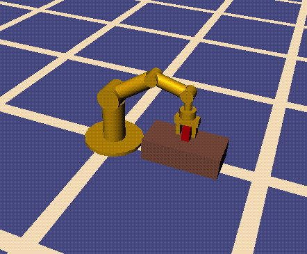
The source code of this example is shown in the example section.
By providing a shaded ground plane, sky and scenic, textures, this node can be used to add substance to the void surrounding the scene. Only the first background node encountered is used, and it must be specified in the main file.
If groundColors are specified, then a ground plane is added to the scenegraph at Y = 0 in global coordinate space. If more than one color is specified, then the ground color is interpolates between colors from 0 degrees downward to 90 degrees at the horizon. Similarly, skyColors interpolate from the 90 degree mark to 180 degrees overhead.
A scene may describe a more precise atmosphere and include background scenery in the scenery field. This field is used to add a texture to the scene that is conceptually distant enough that it does not translate with respect to the eyepoint. The texture should be mapped wrapped around a cylinder so that it runs all the way around from Y=0 in global coordinate space.
If multiple URL's are specified then this expresses a descending order of preference, a browser may display a URL for a lower preference file while it is obtaining, or if it is unable to obtain, the higher preference file. See also the section on URNs.
Background{
    groundColors [ ]       # MFColor
       skyColors [ 0 0 0 ] # MFColor
       scenery ""          # MFString
}
Pros:
Issues:
The avatar node is used for user representation - especially in shared multi-user worlds. For details on Avatar nodes refer to the section on multi-user extensions.
FILE FORMAT/DEFAULTS
Avatar {
    id ""                       # SFString
    transform Transform         # SFNode
    whichRep -1                 # SFLong
    <behaviors>
    belongings NULL             # SFNode
    items NULL                  # SFNode
    <representationArtifacts>
}
Behavior nodes are group nodes to combine a set of behavior components. Behavior nodes and components are described in detail in the behavior section.
FILE FORMAT/DEFAULTS
Behavior {
    <fields>
    <triggers>
    <engines>
    <activators>
    <deactivators>
    <sensors>
    <queries>
    <actions>
    <scripts>
}
This node specifies to a browser what objects in the scene should not be navigated through. It is useful to keep viewers from walking through walls in a building, for instance. Collision response is browser defined. For example, when the camera comes sufficiently close to an object to register as a collision, the browser may have the camera bounce off the object, or simply come to a stop.
Since collision with arbitrarily complex geometry is computationally expensive, one method of increasing efficiency is to be able to define an alternate geometry that could serve as a proxy for colliding against. This collision proxy could be as crude as a simple bounding box or bounding sphere, or could be more spohisticated (for example, the convex hull of a polyhedron). This proxy volume is used ONLY to calculate the collision with the viewer and is NOT used for trivial rejection during the computation process. Efficient trivial rejection can be done using hierarchical bounding boxes or some other technique, and its implementation is not specified in the language.
VRML represents collision proxy volumes for objects through the CollideStyle property node. A CollideStyle node sets the collision proxy volume for all the geometry in the scene graph that follows it upto the next CollideStyle node. Like all other properties, the current collision style would be saved and restored by Separators. Like all other shapes, the geometry is defined in object space and is transformed by the current modeling transformation.
CollideStyle contains two fields: collide (a boolean) and proxy (a node). If the value of the collide field is FALSE, then no collision is performed with the affected geometry. If the value of the collide field is TRUE, then the proxy field defines the geometry against which collision testing is done. If the proxy value is undefined or NULL, the actual geometry is collided against. If the proxy value is not NULL, then it contains the geometry that is used in collision computations.
FILE FORMAT/DEFAULTS
     CollideStyle {
          collide       FALSE   # SFBool
          proxy         NULL    # SFNode
     }
This node represents a simple cone whose central axis is aligned with the y-axis. By default, the cone is centered at (0,0,0) and has a size of -1 to +1 in all three directions. The cone has a radius of 1 at the bottom and a height of 2, with its apex at 1 and its bottom at -1. The cone has two parts: the sides and the bottom.
The cone is transformed by the current cumulative transformation and is drawn with the current texture and material.
If the current material binding is PER_PART or PER_PART_INDEXED, the first current material is used for the sides of the cone, and the second is used for the bottom. Otherwise, the first material is used for the entire cone.
When a texture is applied to a cone, it is applied differently to the sides and bottom. On the sides, the texture wraps counterclockwise (from above) starting at the back of the cone. The texture has a vertical seam at the back, intersecting the yz-plane. For the bottom, a circle is cut out of the texture square and applied to the cone's base circle. The texture appears right side up when the top of the cone is rotated towards the -Z axis.
PARTS
     SIDES       The conical part
     BOTTOM      The bottom circular face
     ALL         All parts

FILE FORMAT/DEFAULTS
     Cone {
          parts         ALL     # SFBitMask
          bottomRadius  1       # SFFloat
          height        2       # SFFloat
     }
Connector nodes provide a simple way to extend the range (recipients) of events. In contrast to behavior nodes they are independent of a single artifact and allow to specify a large number of additional event connections within a single node.
Connector {
 eventMask            # MFInput
 sourceRoutes *       # MFAddress
 destinationRoutes *  # MFAddress
 destinations .       # MFAddress
 mode COPY            # SFEnum [COPY, REDIRECT]
}
The events types which should be copied or re-directed are specified by eventMask field. The sourceRoutes and destinationRoutes fields allow to restrict the number of events by specifying senders and recipients of the original events explicitly. Further on, the new or additional recipients of the events have to be specified by the destinations field. The mode field allows one to toggle between creating additional events and re-directing existing events (i.e. the original recipient(s) will not receive the message).
This node defines a set of 3D coordinates to be used by a subsequent IndexedFaceSet, IndexedLineSet, or PointSet node. This node does not produce a visible result during rendering; it simply replaces the current coordinates in the rendering state for subsequent nodes to use.
FILE FORMAT/DEFAULTS
     Coordinate3 {
          point  0 0 0  # MFVec3f
     }
In VRML 2.0 coordinates are specified by the coords field of IndexedFaceSet, IndexedLineSet and PointSet nodes. Sharing of coordinates is now provided by the extended instancing mechanism.
This node represents a cuboid aligned with the coordinate axes. By default, the cube is centered at (0,0,0) and measures 2 units in each dimension, from -1 to +1. The cube is transformed by the current cumulative transformation and is drawn with the current material and texture. A cube's width is its extent along its object-space X axis, its height is its extent along the object-space Y axis, and its depth is its extent along its object-space Z axis.
If the current material binding is PER_PART, PER_PART_INDEXED, PER_FACE, or PER_FACE_INDEXED, materials will be bound to the faces of the cube in this order: front (+Z), back (-Z), left (-X), right (+X), top (+Y), and bottom (-Y).
Textures are applied individually to each face of the cube; the entire texture goes on each face. On the front, back, right, and left sides of the cube, the texture is applied right side up. On the top, the texture appears right side up when the top of the cube is tilted toward the camera. On the bottom, the texture appears right side up when the top of the cube is tilted towards the -Z axis.
FILE FORMAT/DEFAULTS
     Cube {
          width   2     # SFFloat
          height  2     # SFFloat
          depth   2     # SFFloat
     }
This node represents a simple capped cylinder centered around the y-axis. By default, the cylinder is centered at (0,0,0) and has a default size of -1 to +1 in all three dimensions. The cylinder has three parts: the sides, the top (y = +1) and the bottom (y = -1). You can use the radius and height fields to create a cylinder with a different size.
The cylinder is transformed by the current cumulative transformation and is drawn with the current material and texture.
If the current material binding is PER_PART or PER_PART_INDEXED, the first current material is used for the sides of the cylinder, the second is used for the top, and the third is used for the bottom. Otherwise, the first material is used for the entire cylinder.
When a texture is applied to a cylinder, it is applied differently to the sides, top, and bottom. On the sides, the texture wraps counterclockwise (from above) starting at the back of the cylinder. The texture has a vertical seam at the back, intersecting the yz-plane. For the top and bottom, a circle is cut out of the texture square and applied to the top or bottom circle. The top texture appears right side up when the top of the cylinder is tilted toward the +Z axis, and the bottom texture appears right side up when the top of the cylinder is tilted toward the -Z axis.
PARTS
     SIDES   The cylindrical part
     TOP     The top circular face
     BOTTOM  The bottom circular face
     ALL     All parts
FILE FORMAT/DEFAULTS
     Cylinder {
          parts   ALL   # SFBitMask
          radius  1     # SFFloat
          height  2     # SFFloat
     }
This node defines a sound source that is located at a specific 3D location and that emits primarily along a given direction. It adds directionality to the PointSound node. Besides the direction vector, there are minAngle and maxAngle fields that specify how the intensity of the sound changes with direction. Within the cone whose apex is the sound location, whose axis is the direction vector, and whose angle is specified by minAngle, the DirectedSound behaves exactly like a PointSound. Moving along a constant radius (from the source location) from the surface of this cone to the surface of the similar cone whose angle is maxAngle, the intensity falls off to zero.
See the PointSound node for a description of all other fields.
FILE FORMAT/DEFAULTS
     DirectedSound {
          name              ""         # MFString
          description       ""         # SFString
          intensity         1          # SFFloat
          location          0 0 0      # SFVec3f
          direction         0 0 1      # SFVec3f
          minRange          10         # SFFloat
          maxRange          10         # SFFloat
          minAngle          0.785398   # SFFloat
          maxAngle          0.785398   # SFFloat
          loop              FALSE      # SFBool
          start             0          # input SFTime
          pause             0          # input SFTime
     }
This node defines a directional light source that illuminates along rays parallel to a given 3-dimensional vector.
A light node defines an illumination source that may affect subsequent shapes in the scene graph, depending on the current lighting style. Light sources are affected by the current transformation. A light node under a separator does not affect any objects outside that separator.
FILE FORMAT/DEFAULTS
     DirectionalLight {
          on         TRUE       # SFBool
          intensity  1          # SFFloat
          color      1 1 1      # SFColor
          direction  0 0 -1     # SFVec3f
     }
This node creates a rectangular grid with varying heights, especially useful in modeling terrain and other space creating surfaces. The model is specified primarily by a scalar array of height values that describe the height of the surface above each point of the grid.
The verticesPerRow and verticesPerColumn fields define the number of grid points in the Z and X directions, respectively, defining a surface that contains (verticesPerRow-1) x (verticesPerColumn-1) rectangles.
The vertex locations for the rectangles are defined by the height field and the gridStep field. The vertex corresponding to the i th row and j th column is placed at (gridStep[0] * j, heights[i*verticesPerColumn+j], gridStep[1] * i) in object space, where 0<=i<=verticesPerRow, 0<=j<=verticesPerColumn.
The height field is an array of scalar values representing the height above the grid for each vertex. The height values are stored so that row 0 is first, followed by rows 1, 2, ... verticesPerRow. Within each row, the height values are stored so that column 0 is first, followed by columns 1, 2, ... verticesPerColumn. The rows have fixed Z values, with row 0 having the smallest Z value. The columns have fixed X values, with column 0 having the smallest X value.
The default texture coordinates will range from [0,0] at the first vertex to [1,1] at the far side of the diagonal. The S texture coordinate will be aligned with X and the T texture coordinate with Z.
Treatment of the current material and normal binding is as follows: The PER_PART binding specifies a material or normal for each row of the mesh. The PER_FACE binding specifies a material or normal for each quadrilateral. The _INDEXED bindings are equivalent to their non-indexed counterparts. The default material binding is OVERALL. The default normal binding is PER_VERTEX.
If any normals (or materials) are specified, it is assumed you provide the correct number of them, as indicated by the binding. You will see unexpected results if you specify fewer normals (or materials) than the shape requires. If no normals are specified, they will be generated automatically.
By default, the rectangles are defined with a counterclockwise ordering, so the Y component of the normal is positive. Setting the vertexOrdering field of the current ShapeHints node to CLOCKWISE reverses the normal direction. Backface culling can be turned on as for all shapes, by defining a ShapeHints node prior to the ElevationGrid node with the vertexOrdering field set to CLOCKWISE or COUNTERCLOCKWISE and the shapeType field set to SOLID.
FILE FORMAT/DEFAULTS
     ElevationGrid {
          verticesPerRow 0    # SFLong
          verticesPerColumn 0 # SFLong
          gridStep []         # SFVec2f
          height []           # MFFloat
     }
Pros:
This node describes global environmental attributes such as ambient lighting, light attenuation, and fog.
Ambient lighting is the amount of extra light impinging on each surface point. It is specified as an ambientColor and ambientIntensity. Light attenuation affects all subsequent lights in a scene. It is a quadratic function of distance from a light source to a surface point. The three coefficients are specified in the attenuation field. Attenuation works only for light sources with a fixed location, such as point and spot lights. The ambient lighting and attenuation calculations are defined in the OpenGL lighting model. For a description of these and other lighting calculations, see the description of lighting operations in the OpenGL Specification.
Fog has one of four types, each of which blends each surface point with the specified fog color. Each type interprets the visibility field to be the distance at which fog totally obscures objects. A visibility value of 0 (the default) causes the Environment node to set up fog so that the visibility is the distance to the far clipping plane of the current camera. For more details on the fog calculations, see the description of fog in the OpenGL Specification.
FOGTYPE
     NONE   No fog
     HAZE   Linear increase in opacity with distance
     FOG    Exponential increase in opacity
     SMOKE  Exponential squared increase in opacity

FILE FORMAT/DEFAULTS
     Environment {
          ambientIntensity  0.2        # SFFloat
          ambientColor      1 1 1      # SFColor
          attenuation       0 0 1      # SFVec3f
          fogType           NONE       # SFEnum
          fogColor          1 1 1      # SFColor
          fogVisibility     0          # SFFloat
     }
This node defines the current font style used for all subsequent AsciiText. Font attributes only are defined. It is up to the browser to assign specific fonts to the various attribute combinations. The size field specifies the height (in object space units) of glyphs rendered and determines the vertical spacing of adjacent lines of text.
FAMILY
     SERIF       Serif style (such as TimesRoman)
     SANS        Sans Serif Style (such as Helvetica)
     TYPEWRITER  Fixed pitch style (such as Courier)
STYLE
     NONE        No modifications to family
     BOLD        Embolden family
     ITALIC      Italicize or Slant family
FILE FORMAT/DEFAULTS
     FontStyle {
          size     10      # SFFloat
          family   SERIF   # SFEnum
          style    NONE    # SFBitMask
     }
In VRML 2.0 the font style is specified by the size, family and style fields of the Text node.
This is a node for parametrically describing numerous families of shapes: extrusions (along an axis or an arbitrary path), surfaces of revolution, and bend/twist/taper objects.
General Cylinders are defined by four piecewise linear curves: crossSection, profile, spine and twist. Shapes are constructed as follows. The crossSection is a 2D curve that is scaled, extruded through space, and twisted by the other curves. First, the crossSection is extruded and scaled along the path of the profile curve. Second, the shape is bent and stretched so that its central axis aligns with the spine curve. Finally, the shape is twisted about the spine by angles (in radians) given by the twist curve. The twist curve is a function of angle at given parametric distances along the spine.
Surfaces of Revolution: If the crossSection is a circle and the spine is straight, then the General Cylinder will be equivalent to a surface of revolution, where the General Cylinder profile curve maps directly to that of the surface of revolution.
Cookie-Cutter Extrusions: If both the profile and spine are straight, then the crossSection acts like a cookie-cutter, with the thickness of the cookie equal to the length of the spine.
Bend/Twist/Taper objects: Shapes like this are the result of utilizing all four curves. The spine curve bends the shape, the twist curve twists it, and the profile curve tapers it.
Planar TOP and BOTTOM surfaces will be generated when the crossSection is closed (i.e., when the first and last points of the crossSection are equal). However, if the profile is also closed, the TOP and BOTTOM are not generated; this is because a closed crossSection extruded along a closed profile creates a shape that is closed without the addition of TOP and BOTTOM parts.
The parts field determines which parts are rendered. The notion of BOTTOM versus TOP is determined by the profile curve. The end of the profile curve with a lesser y value is the BOTTOM end.
The cone is transformed by the current cumulative transformation and is drawn with the current texture and material. The first material in the state is used for the entire GeneralCylinder, regardless of the current material binding.
GeneralCylinder automatically generates its own normals. NormalBinding in the state is ignored. Orientation of the normals is determined by the vertex ordering of the triangles generated by GeneralCylinder. The vertex ordering is in turn determined by the crossSection curve. If the crossSection is drawn counterclockwise, then the polygons will have counterclockwise ordering when viewed from the 'outside' of the shape (and vice versa for clockwise ordered crossSections). The General Cylinder responds to the fields of the ShapeHints node the same way as IndexedFaceSet.
Texture coordinates are automatically generated by General Cylinders. These will map textures like the label on a soup can: the coordinates will range in the u direction from 0 to 1 along the crossSection curve and in the v direction from 0 to 1 along the spine. If the TOP and/or BOTTOM exist, textures map onto them in a planar fashion.
When a texture is applied to a General Cylinder, it is applied differently to the sides, top, and bottom. On the sides, the texture wraps [0,1] of the u-direction of the texture along the crossSection from first point to last; it wraps [0,1] of the v-direction of the texture along the direction of the spine, from first point to last. When the crossSection is closed, the texture has a seam that follows the line traced by the crossSection's start/end point as it travels along the spine. For the top and bottom, the crossSection is cut out of the texture square and applied to the top or bottom circle. The top and bottom textures' u and v directions correspond to the x and z directions in which the crossSection coordinates are defined.
PARTS
     SIDES   The extruded surface part
     TOP     The top cross sectional face
     BOTTOM  The bottom cross sectional face
     ALL     All parts

FILE FORMAT/DEFAULTS
     GeneralCylinder {
          spine [ 0 0 0, 0 1 0 ]                  # MFVec3f
          crossSection [ -1 1, -1 -1, 1 -1, 1 1 ] # MFVec2f
          profile [ 1 -1, 1 1 ]                   # MFVec2f
          twist [ 0 -1, 0 1 ]                     # MFVec2f
          parts   ALL                             # SFBitMask
     }
This node represents a 3D shape formed by constructing faces (polygons) from vertices located at the current coordinates. IndexedFaceSet uses the indices in its coordIndex field to specify the polygonal faces. An index of -1 indicates that the current face has ended and the next one begins.
The vertices of the faces are transformed by the current transformation matrix.
Treatment of the material (specified by the materialBinding field) and normal binding (specified by normalBinding field) is as follows: The PER_PART and PER_FACE bindings specify a material or normal for each face. PER_VERTEX specifies a material or normal for each vertex. The corresponding _INDEXED bindings are the same, but use the materialIndex or normalIndex indices. The DEFAULT material binding is equal to OVERALL. The DEFAULT normal binding is equal to PER_VERTEX_INDEXED; if insufficient normals exist in the state, vertex normals will be generated automatically.
Explicit texture coordinates (as defined by textureCoords) may be bound to vertices of an indexed shape by using the indices in the textureCoordIndex field. As with all vertex-based shapes, if there is a current texture but no texture coordinates are specified, a default texture coordinate mapping is calculated using the bounding box of the shape. The longest dimension of the bounding box defines the S coordinates, and the next longest defines the T coordinates. The value of the S coordinate ranges from 0 to 1, from one end of the bounding box to the other. The T coordinate ranges between 0 and the ratio of the second greatest dimension of the bounding box to the greatest dimension.
Be sure that the indices contained in the coordIndex, materialIndex, normalIndex, and textureCoordIndex fields are valid with respect to the current state, or errors will occur.
FILE FORMAT/DEFAULTS
     IndexedFaceSet {
          coords            [ ]         # MFVec3f
          normals           [ ]         # MFVec3f
          textureCoords     [ ]         # MFVec2f
          materialBinding   OVERALL     # SFEnum
          normalBinding     DEFAULT     # SFEnum
          coordIndex        0           # MFLong
          materialIndex     -1          # MFLong
          normalIndex       -1          # MFLong
          textureCoordIndex -1          # MFLong
          verticesCcw       TRUE        # SFBool
          solid             TRUE        # SFBool
          convex            TRUE        # SFBool
          creaseAngle       0           # SFFloat
     }
See Coordinate3 for a description of the coords field, Normal for a description of normals field, TextureCoordinate2 for a description of the textureCoords field, MaterialBinding for a description of the materialBinding field, and NormalBinding for a description of the normalBinding field.See TextureCoordinate2 for a description of the textureCoords field. The verticesCcw, solid, convex and creaseAngle fields replace the the information provided by the vertexOrdering, shapeType, faceType and creaseAngle fields of ShapeHints nodes in VRML 1.0.
This node represents a 3D shape formed by constructing polylines from vertices located at the current coordinates. IndexedLineSet uses the indices in its coordIndex field to specify the polylines. An index of -1 indicates that the current polyline has ended and the next one begins.
The coordinates of the line set are transformed by the current cumulative transformation.
Treatment of the current material (specified by the materialBinding field) and normal binding (specified by normalBinding field) is as follows: The PER_PART binding specifies a material or normal for each segment of the line. The PER_FACE binding specifies a material or normal for each polyline. PER_VERTEX specifies a material or normal for each vertex. The corresponding _INDEXED bindings are the same, but use the materialIndex or normalIndex indices. The DEFAULT material binding is equal to OVERALL. The DEFAULT normal binding is equal to PER_VERTEX_INDEXED; if insufficient normals exist in the state, the lines will be drawn unlit. The same rules for texture coordinate generation as IndexedFaceSet are used.
FILE FORMAT/DEFAULTS
     IndexedLineSet {
          coords            [ ]         # MFVec3f
          normals           [ ]         # MFVec3f
          textureCoords     [ ]         # MFVec2f
          materialBinding   OVERALL     # SFEnum
          normalBinding     DEFAULT     # SFEnum
          coordIndex         0          # MFLong
          materialIndex      -1         # MFLong
          normalIndex        -1         # MFLong
          textureCoordIndex  -1         # MFLong
     }
See Coordinate3 for a description of the coords field, Normal for a description of normals field, TextureCoordinate2 for a description of the textureCoords field, MaterialBinding for a description of the materialBinding field, and NormalBinding for a description of the normalBinding field.See TextureCoordinate2 for a description of the textureCoords field.
This class defines an information node in the scene graph. This node has no effect during traversal. It is used to store information in the scene graph, typically for browser-specific purposes, copyright messages, or other strings.
     Info {
          string  "<Undefined info>"      # SFString
     }
Interfaces provide a simple but very powerful mechanism to establish connections between the scene graph and external applications. These applications might be located on the local host or even on arbitrary external servers. The communication is realized by the common event interface. Events sent to interface node are forwarded to the application or server by the browser. And events sent to browser by the application or server are sent to the Interface node. Since arbitrary user events can be created and any changes of the scene graph can be realized by appropriate events, this interface is powerful enough for almost all kinds of applications. Locating an application on a central server which might be accessed from different VRML worlds allows to create high-level services. The interface node allows behaviors defined within the scene graph to access such services.
Interface {
 direction IN         # SFBitMask [IN, OUT, INOUT]
 forward              # MFAddress
 service ""           # SFString
 name ""              # SFString
}
The interface may be used for input, output or bi-directional I/O. This is specified by direction. The service field specifies the external service associated with the interface node. This might be the name of an application, etc. Incoming events (from outside the scene graph) with unspecified recipients are forwarded to the addresses specified in the forward field. Actually most external applications or servers will specify the service only, since they do not have any information on the current scene graph. The name field finally can be used for the name of an external server (e.g. orgwis.gmd.de/VR or 129.62.47.11), providing the specified service.
An example for an application based on an Interface node is given in the example section.
This node is used to allow browsers to switch between various representations of objects automatically. The children of this node typically represent the same object or objects at varying levels of detail, from highest detail to lowest. LOD acts as a Separator, not allowing properties underneath it to affect nodes that come after it in the scene.
The distance from the viewpoint (transformed into the local coordinate space of the LOD node) to the specified center point of the LOD is calculated. If the distance is less than the first value in the ranges array, then the first child of the LOD is drawn. If between the first and second values in the ranges array, the second child is drawn, etc. If there are N values in the ranges array, the LOD group should have N+1 children. Specifying too few children will result in the last child being used repeatedly for the lowest levels of detail; if too many children are specified, the extra children will be ignored. Each value in the ranges array should be less than the previous value, otherwise results are undefined. Not specifying any values in the ranges array (the default) is a special case that indicates that the browser may decide which child to draw to optimize rendering performance.
Authors should set LOD ranges so that the transitions from one level of detail to the next are barely noticeable. Browsers may adjust which level of detail is displayed to maintain interactive frame rates, to display an already-fetched level of detail while a higher level of detail (contained in a WWWInline node) is fetched, or might disregard the author-specified ranges for any other implementation-dependent reason. Authors should not use LOD nodes to emulate simple behaviors, because the results will be undefined. For example, using an LOD node to make a door appear to open when the user approaches probably will not work in all browsers.
For best results, specify ranges only where necessary, and nest LOD nodes with and without ranges. For example:
       LOD {
            range [100, 1000]

            LOD {
                 Separator { ... detailed version...  }
                 DEF LoRes Separator { ... less detailed version... }
            }
            USE LoRes
            Info { } # Display nothing
       }
In this example, nothing at all will be displayed if the viewer is farther than 1,000 meters away from the object. A low-resolution version of the object will be displayed if the viewer is between 100 and 1,000 meters away, and either a low-resolution or a high-resolution version of the object will be displayed when the viewer is closer than 100 meters from the object.
FILE FORMAT/DEFAULTS
     LOD {
          range [ ]    # MFFloat
          center 0 0 0  # SFVec3f
     }
This node defines the current surface material properties for all subsequent shapes. Material sets several components of the current material during traversal. Different shapes interpret materials with multiple values differently. To bind materials to shapes, use a MaterialBinding node.
The lighting parameters defined by the Material node are the same parameters defined by the OpenGL lighting model. For a rigorous mathematical description of how these parameters should be used to determine how surfaces are lit, see the description of lighting operations in the OpenGL Specification. Note that VRML 1.1 provides no mechanism for controlling the amount of ambient light in the scene, so use of the ambientColor field is browser dependent. Several other parameters (such as light attenuation factors) are also left as implementation details in VRML. Also note that OpenGL specifies the specular exponent as a non-normalized 0-128 value, which is specified as a normalized 0-1 value in VRML (simply multiplying the VRML value by 128 to translate to the OpenGL parameter).
For rendering systems that do not support the full OpenGL lighting model, the following simpler lighting model is recommended:
A transparency value of 0 is completely opaque, a value of 1 is completely transparent. Browsers need not support partial transparency, but should support at least fully transparent and fully opaque surfaces, treating transparency values >= 0.5 as fully transparent.
Specifying only emissiveColors and zero diffuse, specular, emissive, and ambient colors is the way to specify pre-computed lighting. It is expected that browsers will be able to recognize this as a special case and optimize their computations. For example:
Material {
    ambientColor [] diffuseColor [] specularColor []
    emissiveColor [ 0.1 0.1 0.2, 0.5 0.8 0.8 ]
}
Material nodes may contain more than one material. This node specifies how the current materials are bound to shapes that follow in the scene graph. Each shape node may interpret bindings differently. For example, a Sphere node is always drawn using the first material in the material node, no matter what the current MaterialBinding, while a Cube node may use six different materials to draw each of its six faces, depending on the MaterialBinding.
The bindings for faces and vertices are meaningful only for shapes that are made from faces and vertices. Similarly, the indexed bindings are only used by the shapes that allow indexing.
When multiple material values are needed by a shape, the previous Material node should at least as many materials as are needed, otherwise results are undefined.
Issues for low-end rendering systems. Some renderers do not support per-vertex materials, in which case the MaterialBinding values PER_VERTEX and PER_VERTEX_INDEXED will produce upredictable results in different browsers.
BINDINGS
     DEFAULT            Use default binding
     OVERALL            Whole object has same material
     PER_PART           One material for each part of object
     PER_PART_INDEXED   One material for each part, indexed
     PER_FACE           One material for each face of object
     PER_FACE_INDEXED   One material for each face, indexed
     PER_VERTEX         One material for each vertex of object
     PER_VERTEX_INDEXED One material for each vertex, indexed
FILE FORMAT/DEFAULTS
     MaterialBinding {
          value  OVERALL        # SFEnum
     }
In VRML 2.0 material binding is specified by the materialBinding field of IndexedFaceSet, IndexedLineSet and PointSet nodes.
This node defines a geometric 3D transformation with a 4 by 4 matrix. Only matrices that are the result of rotations, translations, and non-zero (but possibly non-uniform) scales must be supported. Non-invertable matrices should be avoided.
Matrices are specified in row-major order, so, for example, a MatrixTransform representing a translation of 6.2 units along the local Z axis would be specified as:
MatrixTransform { matrix
    1 0 0 0
    0 1 0 0
    0 0 1 0
    0 0 6.2 1
}

FILE FORMAT/DEFAULTS
     MatrixTransform {
          matrix  1 0 0 0       # SFMatrix
                  0 1 0 0
                  0 0 1 0
                  0 0 0 1
     }
This node contains information for the viewer through several fields: type, speed, collisionRadius, and headlight.
The type field specifies a navigation paradigm to use. The types that all VRML viewers should support are "walk", "examiner", "fly", and "none". A "walk" viewer would constrain the user to a plane (x-z), suitable for architectural walkthroughs. An "examiner" viewer would let the user tumble the entire scene, suitable for examining single objects. A "fly" viewer would provide six degree of freedom movement. The "none" choice removes all viewer controls, forcing the user to navigate using only WWWAnchors linked to viewpoints. The type field is multi-valued so that authors can specify fallbacks in case a browser does not understand a given type.
The speed is the rate at which the viewer travels through a scene in meters per second. Since viewers may provide mechanisms to travel faster or slower, this should be the default or average speed of the viewer. In an examiner viewer, this only makes sense for panning and dollying - it should have no affect on the rotation speed.
The collisionRadius field specifies the smallest allowable distance between the camera position and any collision object (as specified by CollideStyle) before a collision is detected.
The headlight field specifies whether a browser should turn a headlight on. A headlight is a directional light which always points in the direction the camera is looking. This effect can be had by adding a DirectionalLight in front of a Camera in the scene. Instead, setting this field to TRUE allows the browser to provide a headlight possibly with user interface controls to turn it on and off. Scenes that enlist precomputed lighting (e.g. radiosity solutions) can specify the headlight off here. The headlight should have intensity 1, color 1 1 1, and direction 0 0 -1. The effects of specifying headlight on in a NavigationInfo node are equivalent to an author adding a default DirectionalLight in front of a camera in the scene, except that using the NavigationInfo field allows a browser to provide user interface controlling the light.
FILE FORMAT/DEFAULTS
     NavigationInfo {
          type             "walk"      # MFString
          speed            1.0         # SFFloat
          collisionRadius  1.0         # SFFloat
          headlight        TRUE        # SFBool
     }
This node defines a set of 3D surface normal vectors to be used by vertex-based shape nodes (IndexedFaceSet, IndexedLineSet, PointSet) that follow it in the scene graph. This node does not produce a visible result during rendering; it simply replaces the current normals in the rendering state for subsequent nodes to use. This node contains one multiple-valued field that contains the normal vectors.
To save network bandwidth, it is expected that implementations will be able to automatically generate appropriate normals if none are given. However, the results will vary from implementation to implementation.
FILE FORMAT/DEFAULTS
     Normal {
          vector  [ ] # MFVec3f
     }
In VRML 2.0 normal coordinates are specified by the normals field of IndexedFaceSet, IndexedLineSet and PointSet nodes.
This node specifies how the current normals are bound to shapes that follow in the scene graph. Each shape node may interpret bindings differently.
The bindings for faces and vertices are meaningful only for shapes that are made from faces and vertices. Similarly, the indexed bindings are only used by the shapes that allow indexing. For bindings that require multiple normals, be sure to have at least as many normals defined as are necessary; otherwise, errors will occur.
BINDINGS
     DEFAULT            Use default binding
     OVERALL            Whole object has same normal
     PER_PART           One normal for each part of object
     PER_PART_INDEXED   One normal for each part, indexed
     PER_FACE           One normal for each face of object
     PER_FACE_INDEXED   One normal for each face, indexed
     PER_VERTEX         One normal for each vertex of object
     PER_VERTEX_INDEXED One normal for each vertex, indexed

FILE FORMAT/DEFAULTS
     NormalBinding {
          value  DEFAULT        # SFEnum
     }
In VRML 2.0 normal binding is specified by the normalBinding field of IndexedFaceSet, IndexedLineSet and PointSet nodes.
An orthographic camera defines a parallel projection from a viewpoint. This camera does not diminish objects with distance, as a PerspectiveCamera does. The viewing volume for an orthographic camera is a rectangular parallelepiped (a box).
By default, the camera is located at (0,0,1) and looks along the negative z-axis; the position and orientation fields can be used to change these values. The height field defines the total height of the viewing volume.
A camera can be placed in a VRML world to specify the initial location of the viewer when that world is entered. VRML browsers will typically modify the camera to allow a user to move through the virtual world.
The results of traversing multiple cameras are undefined; to ensure consistent results, place multiple cameras underneath one or more Switch nodes, and set the Switch's whichChild fields so that only one is traversed. By convention, these non-traversed cameras may be used to define alternate entry points into the scene; these entry points may be named by simply giving the cameras a name (using DEF); see the specification of WWWAnchor for a conventional way of specifying an entry point in a URL.
Cameras are affected by the current transformation, so you can position a camera by placing a transformation node before it in the scene graph . The default position and orientation of a camera is at (0,0,1) looking along the negative z-axis, with the positive y-axis up.
The position and orientation fields of a camera are sufficient to place a camera anywhere in space with any orientation. The orientation field can be used to rotate the default view direction (looking down -z-, with +y up) so that it is looking in any direction, with any direction 'up'.
The focalDistance field defines the point the viewer is looking at, and may be used by a browser as a navigational hint to determine how fast the viewer should travel, which objects in the scene are most important, etc.
The nearDistance and farDistance are distances from the viewpoint (in the camera's coordinate system); objects closer to the viewpoint than nearDistance or farther from the viewpoint than farDistance should not be seen. Browsers may treat these values as hints, and may decide to adjust them as the viewer moves around the scene.
FILE FORMAT/DEFAULTS
     OrthographicCamera {
          position         0 0 1        # SFVec3f
          orientation      0 0 1  0     # SFRotation
          focalDistance    5            # SFFloat
          height           2            # SFFloat
          nearDistance     1            # SFFloat
          farDistance      10           # SFFloat
     }
Issues for low-end rendering systems. Most low-end rendering systems do not support the concept of focalDistance. Also, cameras are global to the scene; placing a camera beneath a particular Separator is equivalent to placing it at outermost scope. For broadest compatibility, cameras should only be placed at outermost scope.
A perspective camera defines a perspective projection from a viewpoint. The viewing volume for a perspective camera is a truncated right pyramid.
By default, the camera is located at (0,0,1) and looks along the negative z-axis; the position and orientation fields can be used to change these values. The heightAngle field defines the total vertical angle of the viewing volume.
See more on cameras in the OrthographicCamera description.
FILE FORMAT/DEFAULTS
     PerspectiveCamera {
          position         0 0 1        # SFVec3f
          orientation      0 0 1  0     # SFRotation
          focalDistance    5            # SFFloat
          heightAngle      0.785398     # SFFloat
          nearDistance     1            # SFFloat
          farDistance      10           # SFFloat
     }
This node defines a point light source at a fixed 3D location. A point source illuminates equally in all directions; that is, it is omni- directional.
A light node defines an illumination source that may affect subsequent shapes in the scene graph, depending on the current lighting style. Light sources are affected by the current transformation. A light node under a separator should not affect any objects outside that separator (although some rendering systems do not currently support this).
FILE FORMAT/DEFAULTS
     PointLight {
          on         TRUE       # SFBool
          intensity  1          # SFFloat
          color      1 1 1      # SFColor
          location   0 0 1      # SFVec3f
     }
This node represents a set of points located at the current coordinates. PointSet uses the current coordinates in order, starting at the index specified by the startIndex field. The number of points in the set is specified by the numPoints field. A value of -1 for this field indicates that all remaining values in the current coordinates are to be used as points.
The coordinates of the point set are transformed by the current cumulative transformation. The points are drawn with the current material and texture.
Treatment of the current material (specified by the materialBinding field) and normal binding (specified by normalBinding field) as follows: PER_PART, PER_FACE, and PER_VERTEX bindings bind one material or normal to each point. The DEFAULT material binding is equal to OVERALL. The DEFAULT normal binding is equal to PER_VERTEX. The startIndex is also used for materials or normals when the binding indicates that they should be used per vertex.
FILE FORMAT/DEFAULTS
     PointSet {
          coords          [ ]         # MFVec3f
          normals         [ ]         # MFVec3f
          textureCoords   [ ]         # MFVec2f
          materialBinding OVERALL     # SFEnum
          normalBinding   DEFAULT     # SFEnum
          startIndex      0           # SFLong
          numPoints       -1          # SFLong
     }
See Coordinate3 for a description of the coords field, Normal for a description of normals field, TextureCoordinate2 for a description of the textureCoords field, MaterialBinding for a description of the materialBinding field, and NormalBinding for a description of the normalBinding field.
This node defines a sound source located at a specific 3D location. The name field specifies a URL from which the sound is read. Implementations should support at least the ??? ??? sound file formats. Streaming sound files may be supported by browsers; otherwise, sounds should be loaded when the sound node is loaded. Browsers may limit the maximum number of sounds that can be played simultaneously.
If multiple URL's are specified then this expresses a descending order of preference, a browser may use a URL for a lower preference file while it is obtaining, or if it is unable to obtain, the higher preference file. See also the section on URNs.
The description field is a textual description of the sound, which may be displayed in addition to or in place of playing the sound.
The intensity field adjusts the volume of each sound source; an intensity of 0 is silence and an intensity of 1 is whatever intensity is contained in the sound file.
The sound source has a radius specified by the minRadius field. When the viewpoint is within this radius, the sound's intensity (volume) is constant, as indicated by the intensity field. Outside the minRadius, the intensity drops off to zero at a distance of maxRadius from the source location. If the two radii are equal, the drop-off is sharp and sudden. Otherwise, the drop-off should be proportional to the square of the distance of the viewpoint from the minRadius.
Browsers may also support spatial localizations of sound. However, within minRadius, localization should not occur, so intensity is constant in all channels. Between minRadius and maxRadius, the sound location should be the point on the minRadius sphere that is closest to the current viewpoint. This ensures a smooth change in location when the viewpoint leaves the minRadius sphere. Note also that an ambient sound can therefore be created by using a large minRadius value.
The loop field specifies whether or not the sound is constantly repeated. By default, the sound is played only once.
The start input specifies the time at which the sound should start playing. The pause input may be used to make a sound stop playing some time after it has started. If the pause time is less than the start time then it is ignored. Changing the start input while the sound is playing will result in undefined behavior; however, changing the start input after the sound is paused is well-defined and useful. If the sound is not looped, the length of time the sound plays is determined by the sound file read, and is not specified in the VRML file.
A sound's location in the scene graph determines its spatial location (the sound's location is transformed by the current transformation) and whether or not it can be heard. A sound can only be heard while it is part of the traversed scene; sound nodes underneath LOD nodes or Switch nodes will not be audible unless they are traversed. If it is later part of the traversal again, the sound picks up where it would have been had it been playing continuously.
FILE FORMAT/DEFAULTS
     PointSound {
          name              ""         # MFString
          description       ""         # SFString
          intensity         1          # SFFloat
          location          0 0 0      # SFVec3f
          minRange          10         # SFFloat
          maxRange          10         # SFFloat
          loop              FALSE      # SFBool
          start             0          # input SFTime
          pause             0          # input SFTime
     }
This node defines a 3D rotation about an arbitrary axis through the origin. The rotation is accumulated into the current transformation, which is applied to subsequent shapes.
FILE FORMAT/DEFAULTS
     Rotation {
          rotation  0 0 1  0    # SFRotation
     }
See rotation field description for more information.
This node defines a 3D scaling about the origin. If the components of the scaling vector are not all the same, this produces a non-uniform scale.
FILE FORMAT/DEFAULTS
     Scale {
          scaleFactor  1 1 1    # SFVec3f
     }
Separators should be replaced by Artifacts, to support scene graph optimization by the browser.
This group node performs a push (save) of the traversal state before traversing its children and a pop (restore) after traversing them. This isolates the separator's children from the rest of the scene graph. A separator can include lights, cameras, coordinates, normals, bindings, and all other properties.
Separators can also perform render culling. Render culling skips over traversal of the separator's children if they are not going to be rendered, based on the comparison of the separator's bounding box with the current view volume. Culling is controlled by the renderCulling field. These are set to AUTO by default, allowing the implementation to decide whether or not to cull.
CULLING ENUMS
     ON    Always try to cull to the view volume
     OFF   Never try to cull to the view volume
     AUTO  Implementation-defined culling behavior

FILE FORMAT/DEFAULTS
     Separator {
          renderCulling       AUTO      # SFEnum
     }
The ShapeHints node indicates that IndexedFaceSets are solid, contain ordered vertices, or contain convex faces.
These hints allow VRML implementations to optimize certain rendering features. Optimizations that may be performed include enabling back-face culling and disabling two-sided lighting. For example, if an object is solid and has ordered vertices, an implementation may turn on backface culling and turn off two-sided lighting. If the object is not solid but has ordered vertices, it may turn off backface culling and turn on two-sided lighting.
The ShapeHints node also affects how default normals are generated. When an IndexedFaceSet has to generate default normals, it uses the creaseAngle field to determine which edges should be smoothly shaded and which ones should have a sharp crease. The crease angle is the angle between surface normals on adjacent polygons. For example, a crease angle of .5 radians (the default value) means that an edge between two adjacent polygonal faces will be smooth shaded if the normals to the two faces form an angle that is less than .5 radians (about 30 degrees). Otherwise, it will be faceted.
Issues for low-end rendering systems. The shapeType and vertexOrdering fields are used to determine whether or not to generate back faces for each polygon in a mesh. Most low-end rendering systems do not support built-in back face generation; browsers built on these systems need to create back faces explicitly.
VERTEX ORDERING ENUMS
     UNKNOWN_ORDERING    Ordering of vertices is unknown
     CLOCKWISE           Face vertices are ordered clockwise
                          (from the outside)
     COUNTERCLOCKWISE    Face vertices are ordered counterclockwise
                          (from the outside)
SHAPE TYPE ENUMS
     UNKNOWN_SHAPE_TYPE  Nothing is known about the shape
     SOLID               The shape encloses a volume
FACE TYPE ENUMS
     UNKNOWN_FACE_TYPE   Nothing is known about faces
     CONVEX              All faces are convex
FILE FORMAT/DEFAULTS
     ShapeHints {
          vertexOrdering  COUNTERCLOCKWISE      # SFEnum
          shapeType       SOLID                 # SFEnum
          faceType        CONVEX                # SFEnum
          creaseAngle     0                     # SFFloat
     }
In VRML 2.0 ShapeHints are specified by the vertexCcw, solid, convex and creaseAngle fields of the IndexedFaceSet node.
This node represents a sphere. By default, the sphere is centered at the origin and has a radius of 1. The sphere is transformed by the current cumulative transformation and is drawn with the current material and texture.
A sphere does not have faces or parts. Therefore, the sphere ignores material and normal bindings, using the first material for the entire sphere and using its own normals. When a texture is applied to a sphere, the texture covers the entire surface, wrapping counterclockwise from the back of the sphere. The texture has a seam at the back on the yz-plane.
FILE FORMAT/DEFAULTS
     Sphere {
          radius  1     # SFFloat
     }
This node defines a spotlight light source. A spotlight is placed at a fixed location in 3-space and illuminates in a cone along a particular direction. The intensity of the illumination drops off exponentially as a ray of light diverges from this direction toward the edges of the cone. The rate of drop-off and the angle of the cone are controlled by the dropOffRate and cutOffAngle fields.
A light node defines an illumination source that may affect subsequent shapes in the scene graph, depending on the current lighting style. Light sources are affected by the current transformation. A light node under a separator should not affect any objects outside that separator (although some rendering systems do not currently support this).
FILE FORMAT/DEFAULTS
     SpotLight {
          on           TRUE     # SFBool
          intensity    1        # SFFloat
          color        1 1 1    # SFVec3f
          location     0 0 1    # SFVec3f
          direction    0 0 -1   # SFVec3f
          dropOffRate  0        # SFFloat
          cutOffAngle  0.785398 # SFFloat
     }
Issues for low-end rendering systems. Many low-end renderers do not support the concept of per-object lighting. This means that placing a light beneath a Separator, which implies lighting only the objects beneath the Separator with that light, is not supported in all systems. For the broadest compatibility, lights should only be placed at outermost scope.
This group node traverses one or none of its children. Beside this a Switch node behaves like a Separator.
The whichChild field specifies the index of the child to traverse, where the first child has index 0. This field is an input and thus can be modified by another node.
FILE FORMAT/DEFAULTS
     Switch {
          whichChild  -1        # input SFLong
     }
This node represents one or more text strings specified using the UTF-8 encoding of the ISO10646 character set. This is described below. An important note is that ASCII is a subset of UTF-8, so any ASCII strings are also UTF-8.
The text strings can be rendered in one of four directions: right to left (RL), left to right (LR), top to bottom (TB), or bottom to top (BT). The direction field governs this.
The justification field determines where the text will be positioned in relation to the origin (0,0,0) of the object coordinate system. The values for the justification field are BEGIN, END, CENTER. For a left to right (LR) direction, these would correspond to LEFT, RIGHT, CENTER.
For the directions RL and LR, the first line of text will be positioned with its baseline (bottom of capital letters) at y = 0. The text is positioned on the positive side of the x origin for the direction LR and justification BEGIN; the same for RL END. The text is on the negative side of X for LR END and RL BEGIN. For CENTER justification and horizontal text (RL, LR), each string will be centered at x = 0.
For the directions TB and BT, the first line of text will be positioned with the left side of the glyphs along the y = 0 axis. For TB BEGIN and BT END, the text will be positioned with the top left corner at the origin; for TB END and BT BEGIN, the bottom left will be at the origin. For TB and BT CENTER, the text will be centered vertically at x = 0.
    LR BEGIN    LR END       LR CENTER

  VRML               VRML       VRML
  adds a           adds a      adds a
  dimension!   dimension!    dimension!

    RL BEGIN    RL END       RL CENTER

        LMRV   LMRV            LMRV
      a sdda   a sdda         a sdda
  !noisnemid   !noisnemid    !noisnemid

 TB BEGIN   TB END   TB CENTER     BT BEGIN   BT END   BT CENTER

  V a d         d          d           !     L a !          !
  R d i         i          i           n     M   n          n
  M d m         m        a m           o     R s o        a o
  L s e         e      V d e           i     V d i      L   i
      n       a n      R d n         a s       d s      M s s
    a s       d s      M s s           n       a n      R d n
      i     V d i      L   i       L s e         e      V d e
      o     R s o        a o       M d m         m        a m
      n     M   n          n       R d i         i          i
      !     L a !          !        V a d         d          d
The spacing field determines the spacing between multiple text strings. All subsequent strings advance in either x or y by -( size * spacing). See FontStyle for a description of the size, family and style fields. A value of 0 for the spacing will cause the string to be in the same position. A value of -1 will cause subsequent strings to advance in the opposite direction.
The extent field will limit and scale the text string if the natural length of the string is longer than the extent. If the text string is shorter than the extent, it will not be scaled. The extent is measured horizontally for RL and LR directions; vertically for TB and BT.
UTF-8 character encodings
The 2 byte (UCS-2) encoding of ISO 10646 is identical to the Unicode standard. References for both ISO 10646 and Unicode are given in the references section at the end.
In order to avoid introducing binary data into VRML we have chosen to support the UTF-8 encoding of ISO 10646. This encoding allows ASCII text (0x0..0x7F) to appear without any changes and encodes all characters from 0x80.. 0x7FFFFFFF into a series of six or fewer bytes.
If the most significant bit of the first character is 0, then the remaining seven bits are interpretted as an ASCII character. Otherwise, the number of leading 1 bits will indicate the number of bytes following. There is always a o bit between the count bits and any data.
First byte could be one of the following. The X indicates bits available to
encode the character.

0XXXXXXX  only one byte        0..0x7F (ASCII)
110XXXXX  two bytes            Maximum character value is 0x7FF
1110XXXX  three bytes          Maximum character value is 0xFFFF
11110XXX  four bytes           Maximum character value is 0x1FFFFF
111110XX  five bytes           Maximum character value is 0x3FFFFFF
1111110X  six bytes            Maximum character value is 0x7FFFFFFF

All following bytes have this format: 10XXXXXX
A two byte example. The symbol for a register trade mark is "circled R registered sign" or 174 in both ISO/Latin-1 (8859/1) and ISO 10646. In hexadecimal it is 0xAE; In HTML ®. In UTF-8 it is has the following two byte encoding 0xC2, 0xAE.
The text is transformed by the current cumulative transformation and is drawn with the current material and texture.
Textures are applied to 3D text as follows. The texture origin is at the origin of the first string, as determined by the justification. The texture is scaled equally in both S and T dimensions, with the font height representing 1 unit. S increases to the right, T increases up.
DIRECTION
     LR       Character are drawn from left to right
     RL       Character are drawn from right to left
     TB       Character are drawn from top to bottom
     TB       Character are drawn from bottom to top

JUSTIFICATION
     BEGIN    Align beginning of text to origin
     CENTER   Align center of text to origin
     END      Align end of text to origin

FAMILY
     SERIF       Serif style (such as TimesRoman)
     SANS        Sans Serif Style (such as Helvetica)
     TYPEWRITER  Fixed pitch style (such as Courier)

STYLE
     NONE        No modifications to family
     BOLD        Embolden family
     ITALIC      Italicize or Slant family

FILE FORMAT/DEFAULTS
     Text {
          string         ""    # MFString
          direction      LR    # SFEnum
          justification  BEGIN # SFEnum
          spacing        1     # SFFloat
          width          0     # MFFloat
          size     10          # SFFloat
          family   SERIF       # SFEnum
          style    NONE        # SFBitMask
     }
This property node defines a texture map and parameters for that map. This map is used to apply texture to subsequent shapes as they are rendered.
The texture can be read from the URL specified by the filename field. To turn off texturing, set the filename field to an empty string (""). Implementations should support at least the JPEG image file format. Also supporting GIF and PNG formats is recommended.
If multiple URLs are presented, this expresses a descending order of preference, a browser may display a lower preference URL while the higher order file is not available. See the section on URNs.
Textures can also be specified inline by setting the image field to contain the texture data. Supplying both image and filename fields will result in undefined behavior.
Texture images may be one component (greyscale), two component (greyscale plus transparency), three component (full RGB color), or four-component (full RGB color plus transparency). An ideal VRML implementation will use the texture image to modify the diffuse color and transparency of an object's material (specified in a Material node), then performing any lighting calculations using the rest of the object's material properties with the modified diffuse color to produce the final image. The texture image modifies the diffuse color and transparency depending on how many components are in the image, as follows:
Browsers may approximate this ideal behavior to increase performance. One common optimization is to calculate lighting only at each vertex and combining the texture image with the color computed from lighting (performing the texturing after lighting). Another common optimization is to perform no lighting calculations at all when texturing is enabled, displaying only the colors of the texture image.
WRAP ENUM
     REPEAT  Repeats texture outside 0-1 texture coordinate range
     CLAMP   Clamps texture coordinates to lie within 0-1 range
FILE FORMAT/DEFAULTS
     Texture2 {
          filename    ""        # SFString
          image       0 0 0     # SFImage
          wrapS       REPEAT    # SFEnum
          wrapT       REPEAT    # SFEnum
     }
This node defines a 2D transformation applied to texture coordinates. This affects the way textures are applied to the surfaces of subsequent shapes. The transformation consists of (in order) a non-uniform scale about an arbitrary center point, a rotation about that same point, and a translation. This allows a user to change the size and position of the textures on shapes.
FILE FORMAT/DEFAULTS
     Texture2Transform {
          translation  0 0      # SFVec2f
          rotation     0        # SFFloat
          scaleFactor  1 1      # SFVec2f
          center       0 0      # SFVec2f
     }
This node defines a set of 2D coordinates to be used to map textures to the vertices of subsequent PointSet, IndexedLineSet, or IndexedFaceSet objects. It replaces the current texture coordinates in the rendering state for the shapes to use.
Texture coordinates range from 0 to 1 across the texture. The horizontal coordinate, called S, is specified first, followed by the vertical coordinate, T.
FILE FORMAT/DEFAULTS
     TextureCoordinate2 {
          point  0 0    # MFVec2f
     }
In VRML 2.0 texture coordinates are specified by the textureCoord field of IndexedFaceSet, IndexedLineSet and PointSet nodes.
This node defines a geometric 3D transformation consisting of (in order) a (possibly) non-uniform scale about an arbitrary point, a rotation about an arbitrary point and axis, and a translation. The transform node
Transform {
    translation T1
    rotation R1
    scaleFactor S
    scaleOrientation R2
    center T2
  }
is equivalent to the sequence:
Translation { translation T1 }
Translation { translation T2 }
Rotation { rotation R1 }
Rotation { rotation R2 }
Scale { scaleFactor S }
Rotation { rotation -R2 }
Translation { translation -T2 }
FILE FORMAT/DEFAULTS
     Transform {
          translation       0 0 0       # SFVec3f
          rotation          0 0 1  0    # SFRotation
          scaleFactor       1 1 1       # SFVec3f
          scaleOrientation  0 0 1  0    # SFRotation
          center            0 0 0       # SFVec3f
     }
This node defines a translation by a 3D vector.
FILE FORMAT/DEFAULTS
     Translation {
          translation  0 0 0    # SFVec3f
     }
This node contains information about the world. The title of the world is stored in its own field, allowing browsers to display it for instance in their window border. In order to support shared multi-user worlds, the server field allows the specification of a multi-user server. If multiple server addresses are presented, this expresses a descending order of preference, a browser may use a lower preference server connection if the higher order connection is not available. Any other information about the world can be stored in the info field, for instance the scene author, copyright information, and public domain information.
FILE FORMAT/DEFAULTS
     WorldInfo {
          title         ""      # SFString
          server        ""      # MFString
          info          ""      # MFString
     }
The WWWAnchor group node loads a new scene into a VRML browser when one of its children is chosen. Exactly how a user "chooses" a child of the WWWAnchor is up to the VRML browser; typically, clicking on one of its children with the mouse will result in the new scene replacing the current scene. A WWWAnchor with an empty ("") name does nothing when its children are chosen. The name is an arbitrary URL.
If multiple URLs are presented, this expresses a descending order of preference, a browser may display a lower preference URL if the higher order file is not available. See the section on URNs.
WWWAnchor behaves like a Separator, pushing the traversal state before traversing its children and popping it afterwards.
The description field in the WWWAnchor allows for a friendly prompt to be displayed as an alternative to the URL in the name field. Ideally, browsers will allow the user to choose the description, the URL or both to be displayed for a candidate WWWAnchor.
The WWWAnchor's map field is an enumerated value that can be either NONE (the default) or POINT. If it is POINT then the object-space coordinates of the point on the object the user chose will be added to the URL in the name field, with the syntax "?x,y,z".
A WWWAnchor may be used to take the viewer to a particular viewpoint in a virtual world by specifying a URL ending with "#cameraName", where "cameraName" is the name of a camera defined in the world. For example:
WWWAnchor {
    name "http://www.school.edu/vrml/someScene.wrl#OverView"
    Cube { }
}
specifies an anchor that puts the viewer in the "someScene" world looking from the camera named "OverView" when the Cube is chosen. If no world is specified, then the current scene is implied; for example:
WWWAnchor {
    name "#Doorway"
    Sphere { }
}
will take the viewer to the viewpoint defined by the "Doorway" camera in the current world when the sphere is chosen.
MAP ENUM
     NONE  Do not add information to the URL
     POINT Add object-space coordinates to URL
FILE FORMAT/DEFAULTS
     WWWAnchor {
          name ""        # MFString
          description "" # SFString
          map NONE       # SFEnum
     }
The WWWInline node reads its children from anywhere in the World Wide Web. Exactly when its children are read is not defined; reading the children may be delayed until the WWWInline is actually displayed. A WWWInline with an empty name does nothing. The name is an arbitrary URL.
The effect of referring to a non-VRML URL in a WWWInline node is undefined.
WWWInline behaves like a Separator, pushing the traversal state before traversing its children and popping it afterwards, after the children have been read.
If multiple URL's are specified then this expresses a descending order of preference, a browser may display a URL for a lower preference file while it is obtaining, or if it is unable to obtain, the higher preference file. See also the section on URNs.
If the WWWInline's bboxSize field specifies a non-empty bounding box (a bounding box is non-empty if at least one of its dimensions is greater than zero), then the WWWInline's object-space bounding box is specified by its bboxSize and bboxCenter fields. This allows an implementation to quickly determine whether or not the contents of the WWWInline might be visible. This is an optimization hint only; if the true bounding box of the contents of the WWWInline is different from the specified bounding box results will be undefined.
FILE FORMAT/DEFAULTS
     WWWInline {
          name ""               # MFString
          bboxSize 0 0 0        # SFVec3f
          bboxCenter 0 0 0      # SFVec3f
     }
In VRML 1.0 the DEF mechanism allows to create labels for nodes. These labels can later be used by the USE mechanism to create additional instances of the nodes (i.e. to share the nodes).
The old syntax of the DEF/USE keywords is:
FILE FORMAT
DEF label node { ... }
USE label
Example:
DEF redSphere Separator {
    Material {
        diffuseColor 1.0 0.0 0.0
    }
    Sphere { }
}

USE redSphere           # red sphere will be used again here
While labels created with DEF were not required to be unique in VRML 1.0, they have to be unique in this proposal.
Example:
DEF shape Cube { }
Material { ... }
DEF shape Sphere { }   # NOT ALLOWED
is not allowed. In order to provide a more flexible and more powerful naming mechanism we support hierarchical names by the DEF/USE mechanism.Wolf
DEF shape Cube { }
DEF gadget Separator {
    DEF shape Cube { width 2.0 }   # VALID
}
USE gadget.shape
In our specification we additionally support the naming and sharing of fields. Sharing fields realizes a kind of wired connection, which should be used with caution, since it is not quite as flexible as connections provided by events (see sections about events and event distribution):
DEF nodeLabel node {
    ...
    DEF fieldLable fieldName
    ...
}

node2 {
    ...
    USE nodeLabel.fieldLabel
    ...
}
This mechanisms is especially useful when exposing fields of prototype.
We basically agree with the prototyping style presented as part of the VRML 1.1 proposal by the VAG. However, we think, that some changes and/or improvements are necessary. Some of them are directly related to our behavior proposal (obviously some parts of the current prototype syntax are related to the "Moving Worlds" proposal), some of them are more general in order to provide additional features. One of these features is sub-classing, which allows the creation of new nodes based on existing nodes, without the necessity of using them as child nodes of a new prototype.
The CLASS keyword can be used to define prototypes:
FILE FORMAT
CLASS className {
    fieldType fieldName defaultValue
    ...
    < nodes >
}
The new keyword CLASS is followed by the name of the new node class. This node class name should be unique. Defining an existing node class again (including built-in nodes) is allowed, but requires to define exactly the same fields of the node. This is necessary to guarantee a smooth transition to further extensions.
The node class definition is surrounded by {}. In the first part of the defintion the fields of the new class have to be specified. Sub-nodes are defined right after the field definitions. Field defintions do not require any additional keyword, they require the field type (e.g. SFFloat, SFEnum, etc.) followed by the field name only. Additionally default values can be added after the field name. SFEnum and SFBitMask fields further require a list of all possible values as part of the field name.
Example:
CLASS VRMLLogo {
    Material {
        diffuseColor 1.0 0.0 0.0
    }
    Cube { }
    Translation {
        translation 2.0 0.0 0.0
    }
    Material {
        diffuseColor 0.0 1.0 0.0
    }
    Sphere { }
    Translation {
        translation 2.0 0.0 0.0
    }
    Material {
        diffuseColor 0.0 0.0 1.0
    }
    Cone { }
}
Instances of the new node class can be created by just using them like built-in nodes:
VRMLLogo { }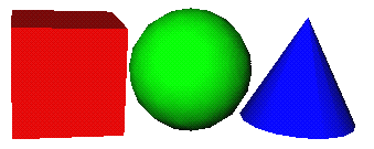
The CLASS mechanism can also be used to inherit new node classes from existing nodes or prototypes:
CLASS className : parentClassName {
    fieldType fieldName defaultValue
    ...
    < nodes >
}
Node classes can be inherited using a more convenient mechanism than specifying the parent node class within the isA field:
CLASS Ball : Sphere {
    SFEnum action [ROLLING, BOUNCING, FALLING] BOUNCING
    SFVec3f speed 0.0 0.0 0.0
}
An instance can be created as shown before:
Ball {
    action FALLING
    speed 0.0 -10.0 0.0
    radius 0.5
}
The CLASS mechanism defines a name space for all field names. Thus, all field names can be used within the CLASS construct without further node specifications. However, if such names are not unique, the full names (nodeName.fieldName) have to be used.
The CLASS mechanism combined with field instancing also allows the support of prototypes like those proposed in the 'Moving Worlds' proposal. (To show this, we use the same example here.)
CLASS TwoColorChair {
    MFColor legColor 0.8 4 0.7
    MFColor seatColor 0.6 0.6 0.1
    Separator {
        DEF seat Material {
            diffuseColor USE legColor
        }
        Cube { ... }
    }
    Separator {
        Transform { ... }
        DEF leg Material {
            diffuseColor USE seatColor
        }
    }
}
In our model it would also be valid to use the new class fields for initialization of the material nodes without the USE keyword:
...
DEF seat Material {
    diffuseColor legColor
}
...
However, using this syntax, the field values are used for initialization only - the fields are not shared as in the example above.
If new node classes are not inherited from existing node classes, they are treated like group nodes. Otherwise they inherit the type from the parent class (shape/property/etc.).
Our behavior approach is entirely based on an object-oriented event model. We achieve a high flexibility by providing the user with built-in event objects and the additional possibility to add arbitrary user-defined events within a VRML file.
This flexible and extendable some advantages:
Finally artifacts sometimes have to send events to inform other parts of the scene graph about the contents (field settings) of their children. Since a single property node is not guaranteed to exist within the internal representation of the browser, such information should only be queried from the corresponding artifact.
The recipients of events are the same groups as the senders. However, most events will be sent to artifacts in order to change their properties (and transformation).
We distinguish six different types of events:
Most of them are very, very simple - the authors do not have to learn any additional syntax to use them.
System events are used to send events generated by the browser/viewer to the scene graph. The most important system events are those generated by user input. Since mouse and keyboard are the most common input devices, these are supported here. More complex input devices such as spaceballs, 3Dmice, glove or speech input can easily be added in the future, if necessary. Additionally any other external input device may be connected to the scene graph using user-defined events, described in one of the subsequent sections.
Events have a syntax similar to nodes. However, events are not part of the scene graph.
FILE FORMAT/DEFAULTS
Mouse {
    button LEFT              # SFBitMask [ NONE, LEFT, MIDDLE, RIGHT ]
    action PRESS             # SFEnum [ NONE, PRESS, RELEASE, ACTION ]
    multiple  1              # SFInt
    posX                     # SFInt
    posY                     # SFInt
    modifier NONE            # SFBitMask [ NONE, SHIFT, CTRL, ALT, META ]
    coordinates 0.0 0.0 0.0  # SFVec3f
}
Mouse events are sent to the artifact chosen by the mouse pointer. They can be handled by that object or any other node higher in the scene graph hierarchy. The button field specifies the button of the mouse which was pressed or released to generate the event. The action field specifies the kind of action performed by the button. Double-clicks, etc. can be detected by the multiple field. The posX and posY fields specify the current window coordinates of the mouse pointer, while the coordinates field specifies the x, y and z value of the mouse pointer in object-space. Finally the modifier field shows the current states of the modifier keys of the keyboard. When a mouse button or modifier key is pressed the mouse pointer is grabbed by the chosen artifact. When moving the mouse pointer, the coordinate field is modified accordingly to the mouse position and the camera position and direction.
FILE FORMAT/DEFAULTS
Key {
    posX                     # SFInt
    posY                     # SFInt
    modifier NONE            # SFBitMask [ NONE, SHIFT, CTRL, ALT, META ]
    key '\0'                 # SFChar
    coordinates 0.0 0.0 0.0  # SFVec3f
}
Key events are also sent to the artifact currently selected by the mouse pointer. That is the reason why most of the fields specific to mouse events are also provided by key events. However, since key events are generated on keyboard inputs, they contain a field specifying the pressed character.
FILE FORMAT/DEFAULTS
Collision {
    opponent      # SFAddress
    type          # SFEnum [ NONE, TOUCH, INTERSECTION, INSIDE, ENCLOSURE ]
}
Collision events are sent to artifacts (and group nodes) with an appropriate flag set. This might be done by a new property node (as proposed by the VRML 1.1 specification). An collision event with type set to NONE is generated, when a former collision has ended.
In addition to the 'visible' fields, events transmit some extra information:
These fields are also used for all other event types. The sender of an event and the time stamp are set automatically. Thus they cannot be changed, but may be used by the recipients of the events to evaluate or reply to events, or to perform different actions depending on the sender. The default recipient of an event is the local artifact (or the current parent node when using other types of group nodes). The recipients field can be set to specify the recipients of an event.
The additional event fields use the following syntax:
FILE FORMAT/DEFAULTS
eventName {
    <eventFields>
    timeStamp     # SFTime (time stamp, when event was sent)
    sender        # SFAddress (sender of the event - read only)
    recipients .  # MFAddress (recipients of the event)
}
Node events transmit all fields of the node, which corresponds to the event. Node events can either be sent to a node of the same type or to group nodes, changing the first child node of the specific type. If no such child node exists, it is added to the group node. In contrast to nodes, events do not have defaults. Thus, if a field is not modified, the event does not modify the corresponding field at the recipient node.
Examples for node events are shown here (the definitions are exactly the same as the corresponding nodes, except the missing default values for the fields):
Transform {
    translation               # SFVec3f
    rotation                  # SFRotation
    scaleFactor               # SFVec3f
    scaleOrientation          # SFRotation
    center                    # SFVec3f
}
Material {
    ambientColor              # MFColor
    diffuseColor              # MFColor
    specularColor             # MFColor
    shininess                 # MFFloat
    transparency              # MFFloat
}
Cube {
    width                     # SFFloat
    height                    # SFFloat
    depth                     # SFFloat
}
Field events transmit the value(s) of a single field. For that reason there is one corresponding field event for every field type. Field events can be sent to appropriate fields of nodes of the same type. Examples for field events are:
SFFloat {
    value 0.0
}
which transmits a single value of type SFFloat, and
SFString {
    value ""
}
which transmits a single value of type SFString.
The general syntax for all field events is:
FILE FORMAT/DEFAULTS
SFfield {
    value defaultValue          # field of type SFfield
}

MFfield {
    values [ defaultValue1,     # field of type MFfield
             defaultValue2,
             ...           ]
}
However, all changes to nodes can already be realized by using node events and specifying (setting) only some or even only a single field value. We additionally allow field events, since they are much smaller (some node events can become very large). Small events are essential for event distribution over a network, which is required to support multi-user worlds.
Query events use the same syntax as node and field events. A query event sent to a node, will force the node to return the corresponding node or field event, with the field(s) set to the current contents. The use of query events to realize complex behavior will be described later on.
Scene graph events are used to add, move, remove and copy single nodes or parts of the scene graph.
FILE FORMAT/DEFAULTS
AddNode {
    node             # SFNode
    label            # SFString
}
The node field specifies the node to be added to the node the event is sent to. This either has to be a group node or an artifact. The label field allows to specify a label for the new node.
FILE FORMAT/DEFAULTS
MoveNode {
    destination      # SFAddress
    label            # SFString
}
This event is sent to a node which is removed from the scene graph and added at the position specified in the destination field. Remember: the original position (from where the node is moved) is specified in the recipient field of the event. This event allows to relocate whole branches of the scene graph by moving group nodes. Additionally this event allows to rename a node (naming without moving is performed by specifying the label field only).
FILE FORMAT/DEFAULTS
RemoveNode {
}
This event removes the node it is sent to from the scene graph. However, if the node is a group node, all child nodes are removed as well.
FILE FORMAT/DEFAULTS
CopyNode {
    destinations     # MFAddress
    label            # MFString
}
This event allows to copy single nodes or parts of the scene graph. Since multiple copies can be specified as part of the destination field, multiple copies may be created by a single event. Names for the new nodes can be specified in the labels field.
FILE FORMAT/DEFAULTS
LinkNode {
    destinations     # MFAddress
    label            # MFString
}
This event allows to create a shared instances of a single node or parts of the scene graph. Since multiple instances can be specified as part of the destination field, multiple instances may be created by a single event. Names for the new nodes can be specified in the labels field. Actually this event create nodes as if they were realized by USE mechanism.
The SFNode field is used, as it was proposed by the VRML 1.1 specification. The SFAddress field specifies nodes within the scene graph. More information on new field types is provided in the appropriate section at the appendix of this document.
Examples of such events are:
AddNode {
    node Separator {
        Transformation { translation 0.0 5.0 0.0 }
        Sphere { radius 2.0 }
    }
    recipients myWorld.mainHall
}

CopyNode {
    recipients myWorld.mainHall.Table.Material
    destination yourWorld.beach.Table
}
EVENT
User defined events are declared like new node classes, using the new EVENT keyword instead of the CLASS keyword. Events do not need to be declared for built-in nodes and fields or nodes defined by a CLASS statement.
FILE FORMAT/DEFAULTS
EVENT eventName {
    <eventFields>
}
Example:
EVENT OpenEvent { }
This user-defined event does not contain any data. Other, more complex events may contain arbitrary data:
EVENT AnimateEvent {
    MFVec3f    translations [ ]
    MFRotation rotations [ ]
    MFFloat    timeSlices [ ]
}
User defined events may also contain default values, which means, that the appropriate fields are always set. It is not possible nor necessary to define user defined field events or query events.
The internal fields (i.e. the sender, the recipients and the time stamp) are added automatically to each event. Thus they do not have to be declared as part of the event definition.
Events very often influence or query the current transformation of the
recipients. This rises the question on how transformations are affected by the
transmission of events. Beside the simple transmission of the field values, such
values might be translated from the coordinate system of the sender to the
coordinate system of the recipient or might entirely be specified as global
coordinates. A simple solution for this problem would be to add another field to
those events, which transmit postions or directions. These are: Transform,
Scale, Translate, Rotate, MatrixTransform, SFVec3f/MFVec3f and
SFRotation/MFRotation events.
The field syntax could be:
transformModifier NONE # SFEnum [NONE, GLOBAL, LOCAL, RELATIVE]
where NONE is the default and transmits the field values as they are. GLOBAL interprets the transmitted values as global values (world coordinates) or returns global values when used for query events. LOCAL interprets the given values as local values and translates them the coordinate system of the recipient, finally RELATIVE values are added to the field values of the recipients, rather than replacing the old values.
Our behavior model is based on a new node class: behavior nodes. Behavior nodes can be attached to artifacts (as child nodes). Nevertheless, it is also possible to use behavior nodes as children of any other group node - although we do not recommend this.
Different behavior nodes, realizing the various behaviors can be cretated by the sub-classing mechanism. It allows the user to define arbitrary new behavior nodes (classes) by combining and tailoring behavior node components. Behavior nodes - whether used to compute user interactions or independent artifact behavior are assembled from a basic set of components. These components are nodes, but can only be used as children of behavior nodes. Components can be subdivided into the classes: triggers, actions, scripts, engines, sensors, activators, deactivators, and queries.
FILE FORMAT/DEFAULTS
CLASS behaviorName {
    <fields>
    <triggers>
    <engines>
    <activators>
    <deactivators>
    <sensors>
    <queries>
    <actions>
    <scripts>
}
By providing specialized or pre-configured realizations of certain components, most common behaviors can be realized with minimal effort. However, more complex behaviors may also be realized by assembling those components - but will usually be based on more powerful, configurable ones.
The definitions of these components includes some new field types, which are introduced in detail in the appendix. The basic functionality of each component (including some possible realizations) is shown in the following subsections.
Additionally, our behavior model includes a behavior node, which can be used to define simple behaviors on the fly. This is done by just adding it to an artifact and defining the sub-components.
FILE FORMAT/DEFAULTS
Behavior {
    <fields>
    <triggers>
    <engines>
    <activators>
    <deactivators>
    <sensors>
    <queries>
    <actions>
    <scripts>
}
All components fields, the specified inputs and outputs (events) and the fields of the behavior node share a single name space. However, if necessary, fields may be specified by using a qualified name (componentClass.fieldName) or additional labels provided by the DEF keyword (componentLabel.fieldName). Single values of multi value fields may be specified by using indeces []. The same mechanism can also be used to specify e.g. the x-value of SFVec3 field.
We decided to use several different components (specialized as well as very general ones) instead of one very powerful scripting component. The reason for that was, that we see VRML not only as a platform for 3D data and virtual worlds created by programmers and scientists, but rather as the base for developments in the areas of art and design. Artists and designers will rather like to model a world (including all the behaviors) than writing scripts, which actually requires the knowledge of a programming language. It might be possible to create those scripts from an authoring tool, thus the author does not need to know anything about scripting, but the resulting files will be hard to unterstand. They would probably contain large segments of code and it would be very hard to reload these files into another graphical authoring tool or to tailore them later on, without the original authoring software.
Since components itself are very simple objects they are predestinated to be assembled to even complex behaviors. Since they consist of valid VRML node fields only, even components not specified when an authoring tool was released can easily be configured. Additionally it is much easier to change or modify small parts of the behavior. This might even be done from wihtin other behaviors.
Trigger components are used to catch events (sent to an artifact) and execute behaviors depending on these events. Some convenience trigger components are available to catch the most common events. All trigger components can be active or inactive, i.e. to temporary disable certain behaviors. Triggers are active by default (i.e. when the virtual world is loaded).
Triggers to catch the most common system events, i.e. mouse and keyboard events, will be provided:
FILE FORMAT/DEFAULTS
MouseTrigger {
    input Mouse mouse                     # SFInput (fixed)
    condition  mouse.button == LEFT &&
               mouse.action == ACTION     # SFCondition
    active TRUE                           # SFBool
}
The MouseTrigger component triggers Mouse events. For that reason the input event type is a Mouse event. The condition field allows the user to specify conditions which have to be satisfied in order to catch the event. The default condition is clicking (ACTION) the left mouse button. More information on the SFCondition field is provided in the appendix.
FILE FORMAT/DEFAULTS
KeyTrigger {
    input Key key    # SFInput (fixed)
    condition        # SFCondition
    active TRUE      # SFBool
}
This trigger works similar to the MouseTrigger, except that keyboard events are triggered. Here the condition field will usually be used to specify the pressed key and to determine the state of the modifier keys.
A general trigger component to catch arbitrary events is also available:
FILE FORMAT/DEFAULTS
Trigger {
    inputs []        # MFInput (no events specified by default)
    condition        # SFCondition (no event - no condition)
    active TRUE      # SFBool
}
This trigger can be used to catch any type of event. Especially it will be used to catch user defined events. Special trigger components, catching a certain event type can easily be added by the prototyping mechanism:
EVENT HighLight {
    SFBool highLight TRUE   # highLight TRUE by default
}
CLASS HighLightTrigger : Trigger {
    inputs HighLight highLight
}
This trigger components will trigger on any HighLight event received. Since no HighLight node exists, the event has to be defined as a user-defined event by the EVENT keyword.
The triggers shown above are sufficient to detect single or multiple events and to realize "and" connections between multiple events. However, "or" connections between several events can also be realized by using several triggers for a single behavior.
Special triggers are used to activate or deactivate the behavior (see sub-section on activators and deactivators).
We can think of much more complex trigger components to support shared interactions in distributed environments, etc. (see section on distributed behavior). Additionally, triggers might be useful, which allow arbitrary and/or combinations within a single component, as well as possibilities to specify time-outs and event orders.
Actions specify the outputs (the outgoing events) of behavior nodes. Thus they allow to specify one or several events and the address of the recipients. The address scheme allows one to send events to single as well as multiple recipients. Since the address also allows wildcards, recipients can also be specified, which were not part of the scene graph, when the behavior was specified.
We prefer using this additional Action component rather than simple output fields attached to the behavior node, since conditions on outputs can easily be checked and more complex actions might be used in the future to realize some simple operations on the incoming events first.
FILE FORMAT/DEFAULTS
Action {
    condition       # SFCondition (no condition - send always)
    outputs []      # MFOutput
}
The default recipient of the events is the local artifact. For behaviors which are not defined as parts of an artifact (we do not encourage this), the local recipient is the parent node. However, any node, which can handle the specified event types, might be used as recipient. Inappropriate recipients of the specified event types will be ignored. The condition field is used to specify conditions which have to be true before an event is sent. By using several action components with different conditions set, more complex behavior can be realized.
The combination of at least one trigger component and one action component allows us to realize a large number of behaviors. We will give some simple examples here:
CLASS MakeBlueBehavior {
   MouseTrigger { }
   Action {
       outputs Material material {     # sending material event
           diffuseColor 0.0 0.0 1.0    # diffuse color set to blue
       }
   }
}
defines a new Behavior node class. Instances of this class can easily be attached to an arbitrary artifact.
Artifact {
    MakeBlueBehavior { }
    Sphere { }
}
The behavior realized by this example will change an artifact's color to blue, when clicking with the left mouse button on it, since clicking the left mouse button is the default event triggered by MouseTrigger component.
Nevertheless it is also very simple to define behavior without prototyping the behavior node, by just adding the behavior definition within a Behavior node to an Artifact node.
Artifact {
    Behavior {
        MouseTrigger {
            condition mouse.button == RIGHT &&
                      mouse.action == DOUBLE
        }
       Action {
           outputs Material material {     # sending material event
               diffuseColor 0.0 0.0 1.0    # to local artifact
           }
       }
    }
    Cube { }
}
To simplify the use of action components, some of them could be realized by pre-configured action components. Those specialized action components can be built-in or they can easily be realized using the CLASS mechanism.
FILE FORMAT/DEFAULTS
TransformAction {
    condition                    # SFCondition
    outputs Transform transform  # SFOutput (fixed input event type)
}
This TransformAction components will send a Transform event. The default recipient is the local artifact.
FILE FORMAT/DEFAULTS
MaterialAction {
    output Material material     # SFOutput (fixed input event type)
    condition                    # SFCondition
}
The MaterialAction sends a Material event.
These two specialized actions seem to be useful, since most behaviors change the transformation and/or the material of a shape.
Script components can be used to embed code of arbitrary languages (supported by the local browser) within behavior nodes. This allows one to realize even applications by these nodes.
FILE FORMAT/DEFAULTS
Script {
    language ""     # SFString
    code ""         # SFString (source code or URL)
    outputs []      # MFOutput
}
Since the script components use the event mechanism as an interface with the scene graph, they can easily be embedded within this approach. Arbitrary scripting languages can be specified by the language field. The browser might use this field to determine the appropriate interpreter or use the MIME type of the script (when using an URL) instead. The code field contain either a piece of code written in the appropriate scripting language, or an URL, which contains the required script. The outputs field is used to specify the output interface of the script node as part of the behavior node rather than within a script (nevertheless a script may sent arbitrary events). This might be important for browser optimization and allows to change to scripting code or even the chosen language later on, without modifications of the interface. In contrast to actions, outputs specified within script nodes are not sent unless specified within the script. Since script nodes are activated by triggers, sensors or engines, input defintions are not part of the script component. A description of the script interface (API) can be found in the appendix.
Example:
DEF RotatingKnives Artifact {
    Behavior {
        Trigger {
            inputs [ Collision col ]
        }
        Script {
            language "java"
            code "http://www.horror.com/java/classes/RotatingKnives"
            outputs [ SFRotation rot ]
        }
    }
    ...     # knive shapes come here ...
}
Another example of a script component is provided in the next sub-section.
To realize autonomous object behavior, e.g. simple animations, velocity or gravity, the trigger component is replaced by the engine component. Engine components trigger behavior objects without any external (user) events, as time passes.
Since engines are timer based triggers, they also have an active field, which stops timer engines from generating further events. Many engines will not only trigger other components of the behavior, but also update certain values, according to the field settings of the engine.
Engine components might be very simple (e.g. to realize the rotation of an object, or even arbitrary complex). We give some possible examples for engine components here:
FILE FORMAT/DEFAULTS
TimerEngine {
    start 0                       # SFTime
    stop 0                        # SFTime
    timeStep 1.0                  # SFFloat
    timeValue                     # SFTime
    duration FALSE                # SFBool
    active TRUE                   # SFBool
}
This very simple engine component realizes a timer. It can be used to trigger a behavior after a certain time (one shot) or trigger it at a certain frequency. If the start time is before the system time (e.g. start time is 0), the timer engines starts triggering as soon as the behavior node is generated. When the time specified by stop is reached, the timer engines will stop triggering. If start and end time are equal - only a single trigger event is generated. If timeStep is 0, two events (one at the start time and one at the end time) are generated. If stop time is later than start time, one trigger is guaranteed to be generated at end time. By default timer engines start triggering at system start-up and continue as long as the behavior node exists. If the duration flag is set, the stop field is interpreted as a duration (time after which the engine will stop). Since most systems cannot guarantee that the timer engine will be evaluated at exactly the time specified, the timeValue field is set with the current time just before the trigger. We will give an example of a TimerEngine triggering a behavior script:
CLASS Rotor {
    SFVec3 axis 0.0 1.0 0.0
    TimerEngine {
        timeStep 0.1
    }
    Script {
       language "python"             # interpreted language
       code "i=0
             from VRML_Lib import *
               def rotate(sender, coords):
                       i = i + 1
                       i = i % 360
                       rotation = SFRotation()
                       rotation.angle = i * 3.14159 / 180.0
                       rotation.axis[0] = coords.value[0]
                       rotation.axis[1] = coords.value[1]
                       rotation.axis[2] = coords.value[2]
                       sendEvent(rotation)

             rotate(axis)
            "
       outputs rotation SFRotation
    }
}
This example shows, that all fields of components as well as the events share a single name space (within the behavior node).
Instances of the Rotor behavior class can now be attached to any artifact:
DEF RotatingPlate Artifact {
    Rotor {
        axis 0.0 0.0 1.0
    }
    Cube {
        width 5.0
        height 0.2
        depth 5.0
    }
}
Animations usually require changes in position and orientation over a certain time. We use a special engine to support this kind of behavior:
FILE FORMAT/DEFAULTS
InterpolationEngine {
    rotations [ 0.0 1.0 0.0 0.0 ] # MFRotation (rotation 0, 1, 2, ...)
    translations [ 0.0 0.0 0.0 ]  # MFRotation (translation 0, 1, 2, ...)
    timeSlices [ ]                # MFFloat (time between frames)
    rotationValue 0.0 1.0 0.0 0.0 # SFRotation (current rotation)
    translationValue 0.0 0.0 0.0  # SFVec3f (current translation)
    timeValue 0.0                 # SFFloat (passed time)
    repeat FALSE                  # SFBool
    return FALSE                  # SFBool
    active TRUE                   # SFBool
}
When the InterpolationEngine becomes active (by default this is after loading the scene), it starts to interpolate between the field values of the rotations and the translations fields respectively. The available time period between two 'frames' is specified by the timeSlices field. The current values of the rotation, translation and time are available in the rotationValue, translationValue and timeValue fields. If there are more rotations or translations than timeSlices, these rotations or translations are ignored. If repeat is FALSE, there should be one time slice value less than rotation and translation values. If there are more time slices than rotations or transformations, the interpolation engine does nothing but increase the timeValue after the last rotation / transformation has been executed. The active field is set to FALSE after the last time slice has been executed and the repeat field is FALSE too. If the return field is TRUE, the time slices are executed again in back-order after the last one is finished.
We can realize the Rotor behavior by an InterpolationEngine:
CLASS Rotor {
    SFVec3 axis 0.0 1.0 0.0
    InterpolationEngine {
        rotations [ axis[0] axis[1] axis[2] 0.0,
                    axis[0] axis[1] axis[2] 6.28 ]
        timeSlices 6.0
        repeat TRUE
    }
    Action {
        outputs Rotation rot {
            rotation rotationValue
        }
    }
}
Another example, using interpolation engines in combination with activators is shown in the next sub-section. A more complex example using engines can be found in the example section of this paper.
Most object behavior in virtual worlds is not independent from other interactions. This means the user cannot do any kind of interaction at any time. Example: A user wants to move an artifact. To do so, he or she first has to grab (select) the artifact, then it might be moved and finally deselected (stopping the movement). Although this is a very common example, which is included within most former proposals as a special interaction style, it can easily be realized by our general approach, which is also applicable to all other interactions which have a certain 'life time'.
To realize this, we use two additional components, which are specialized trigger components. The Activators activate the trigger components of a behavior object while deactivators deactivate them.
FILE FORMAT/DEFAULTS
Activate {
    inputs []       # MFInput (does not recognize any event)
    condition       # SFCondition (no event - no condition)
    active TRUE     # SFBool
}

FILE FORMAT/DEFAULTS
Deactivate {
    inputs []       # MFInput (does not recognize any event)
    condition       # SFCondition (no event - no condition)
    active FALSE    # SFBool
}
Since activators and deactivators are triggers, they also have active fields. All activators are active by default. If the behavior node has at least one activator, the trigger components are deactivated. Deactivators are inactive by default. When at least one activator is triggered, all triggers and deactivators are activated and the activators are deactivated. However, the defaults can be changed by setting the appropriate active fields. Further more the active fields might be set within other components of the behavior node.
A behavior object to realize the given example could look like that:
CLASS Move {
    Activate {
        inputs [ MouseBtn mouseP ]
        condition button == LEFT &&
                  action == PRESS
    }
    Trigger {
        inputs [ Mouse mouseM ]
    }
    Deactivate {
        inputs [ MouseBtn mouseR ]
        condition button == LEFT &&
                  action == RELEASE
    }
    TranslationAction {
        outputs [ Translation trans {translation mouseM.coordinates}]
    }
}
To make an object moveable by the left mouse button, we only have to add the behavior object as subobject to an arbitrary artifact:
Artifact {
    Move { }
    Sphere { }
}
Since Engine components realize the object trigger - they can be activated and deactivated like triggers. This will usually be done by adding appropriate Activate or Deactivate components. See the little guard example in the example section.
Sensor components can be used to simplify behavior definitions. They are used to trigger the behavior object and replace the Trigger or Engine component for that reason. Sensor components are used to detect modifications of nodes or events, which usually would not influence the behavior object.
A sensor can be used to monitor all changes of a certain node or field.
FILE FORMAT/DEFAULTS
Sensor {
    inputs []     # MFInput
    condition     # SFCondition
    active TRUE   # SFBool
}
The input field specifies the events which will be sent on changes to the monitored (sensored) node or node field. The condition field additionally allows one to specify conditions for the values of the received event(s).
The example shows how an artifact (object) can be clued to another one, thus it is moved, when the other artifact "MyCube" is moved (but not vice versa).
CLASS MoveTogether {
    Sensor {
        inputs Transform trans {
            recipients [ *MyCube ]
        }
    }
    Action {
        outputs transform Transform {
            translation trans.translation
        }
    }
}
The recipients field of the transform event specifies the node/field to sensor. Actually a query event is sent to specified node (here a transform query event), which is replied by the node by the corresponding event (here a transform event).
Sensors can also be used to trigger actions depending on the location of the viewer. This can for example be achieved by monitoring the appropriate fields of a camera node. Another possibility is to use an invisible bounding box. In the following example, this allows to realize an automatic door.
DEF AutomaticDoor Artifact{
    Behavior {
        Sensor {
            inputs Collision collision
            condition collision.type == ENTER
        }
        Action {
            outputs OpenEvent open
        }
    }
    Material {
        transparency 1.0       # invisible
    }
    DEF BoundingBox {
        ...
    }
    Artifact {
        Behavior {
            Activate {
            }
            InterpolationEngine {
               translations [ 0.0 0.0 0.0,
                              10.0 0.0 0.0 ]
               timeSlices [ ]
               translationValue 0.0 0.0 0.0
            }
            Action {
                outputs Transform transform {
                    translation translationValue
                }
            }
        ...
        DEF Door Cube {
            ...
        }
    }
}
Since this example does not depend on a camera node, it can recognize abitrary moving objects (avatars, robots, dogs, squirrels, etc.)
Queries work almost like sensors, except they do not generate events automatically when a field value of the sensored node is changed, but rather poll the current field settings each time they are traversed. Query components can be used within behavior components to achieve additional information on nodes and artifacts after the behaviors has been triggered. Query components send an approriate query event to the fields or nodes specified and receive an corresponding node or field event. Only the first recipient fullfilling the specified conditions will return an event. Multiple returning events can be handled by special queries from within script nodes (see scripting interface).
The syntax of a query component is very simple:
FILE FORMAT/DEFAULTS
Query {
    condition           # SFCondition
    inputs []           # MFInput
}
Example:
CLASS RedGreenLight {
    MouseTrigger {
    }
    Query {
        inputs Material material {
        }
    }
    Action {
        outputs Material red {
            diffuseColor 1.0 0.0 0.0
        }
        condition material.diffuseColor == 0.0 1.0 0.0
    }
    Action {
        outputs Material green {
            diffuseColor 0.0 1.0 0.0
        }
        condition material.diffuseColor == 1.0 0.0 0.0
    }
}
This behavior toggles the color of the artifact it is attached to between red and green when clicking with the mouse. Other (more complex) or additional actions could easily be achieved by modifying the outputs of the action components.
Here we show another more general example of a light switch behavior:
CLASS LightSwitchBehavior {
    SFAddress light
    MouseTrigger { }
    Query {
        inputs SFBool isOn {
            recipients (light).on
        }
    }
    Action {
        condition isOn.value == TRUE
        outputs SFBool switchOff {
            value FALSE
            recipients (light)
        }
    }
    Action {
        condition isOff.value == FALSE
        outputs SFBool switchOn {
            value TRUE
            recipients (light)
        }
    }
}
These light switch behavior can be attached to arbitrary artifacts or group nodes. Clicking onthe artifact turns the light on or off respectively. This allows us to model entire switches:
DEF Switch Artifact {
    LightSwitchBehavior {
        light *mainHall.light
    }
    Cube {                     # simple switch shape
        width 0.05
        height 0.05
        depth 0.01
    }
}
Semantic components are not be part of our official proposal, we moved their descriptions to an external document. If you are interested, how complex behavior can be realized on base of an object oriented model without scripting, you should read this document.
These are some ideas on how to extend the behavior model in order to support several users and shared virtual worlds. This approach allows us to support multi-user interactions (several users interact with the same artifact concurrently) as well as synchronized distributed behavior. Despite the fact that support for shared distributed multi-user worlds can be realized within script nodes, it could also easily be integrated within our approach by extending the current event distribution scheme and adding two modified components types:
Our proposal simplifies some of the work needed to realize distributed worlds: events of our behavior model can easily be transmitted over a network. They need only be extended to provide some information on the sending site, which can easily be achieved by adding an additional field.
Shared Trigger components synchronize events, which would actually trigger the behavior, by sending them to their replicated copies. This allows one either to lock certain interactions when already accessed by a different user, or to combine the input events of several users.
FILE FORMAT/DEFAULTS
BlockSharedTrigger {
    inputs []         # MFInput
    timeOut 10000     # SFInt
    condition         # SFCondition (no event - no condition)
    activator         # SFString (SFAddress?)
    active TRUE       # SFBool
}
The BlockSharedTrigger blocks the access to a certain behavior after triggered. Only further events of the same sender (activator) lead to further executions of the behavior. The timeOut is used to specify the time (in milliseconds) when to unlock the trigger and allow events from arbitrary senders again. Of course the time out applies only when the trigger is still active.
FILE FORMAT/DEFAULTS
MultiSharedTrigger {
    inputs []         # MFRegister
    counts []         # MFInt
    timeOut 10        # SFInt
    condition         # SFCondition (no event - no condition)
    active TRUE       # SFBool
}
The MultiSharedTrigger component is used to trigger several events sent to the same behavior node by different browsers (located on different sites). It keeps track of all events with a timestamp within the specified time out interval. All events are removed from the inputs fields after the behavior has been executed. Nevertheless, the trigger component might be able already to store further incoming events, since the execution of the behavior might require more time than the specified time out value.
Synchronized Engines use an approach you might call generalized dead reckoning: The current state is distributed along with a time stamp and the behavior for a certain time in the future (field values which influence the output values of the engine).
One example is a synchronized interpolation engine:
FILE FORMAT/DEFAULTS
InterpolationSyncEngine {
    rotations [ 0.0 1.0 0.0 0.0 ] # MFRotation (rotation 0, 1, 2, ...)
    translations [ 0.0 0.0 0.0 ]  # MFRotation (translation 0, 1, 2, ...)
    timeSlices [ ]                # MFFloat (time slice between two fr.)
    rotationValue 0.0 1.0 0.0 0.0 # SFRotation (current rotation)
    translationValue 0.0 0.0 0.0  # SFVec3f (current translation)
    timeValue 0.0                 # SFFloat (passed time)
    repeat TRUE                   # SFBool
    return TRUE                   # SFBool
    active TRUE                   # SFBool
    sync CYCLE                    # SFEnum [ NEVER, FRAME, STEP, CYCLE ]
}
The only difference between this Engine component and the one used before is the additional sync field. This field forces the engine to send the current timeValue together with a time stamp to a server or communication channel. Synchronization may be off (NEVER), done each frame (each time the engine generates new output events), each step (each step is defined by single value in the timeSlices field) or each cycle. The Engine might also receive such events and reset their output values according to the received values. Since most engines will be deterministic, it is very easy to calculate the accurate current values, if you know the values for a specified time in the future or the past.
In our proposal users can be represented as avatars. Avatars are realized by special artifacts. Avatars influence several aspects of a user: the current shape as well as alternative shapes of the user, the user-specific or shape-specific behavior, the different navigation and camera settings, and items which belong to the user, but are not visible (belongings) and items the user is carrying. Avatars can be specified as recipients of events by their id.
The syntax of an avatar node looks like that:
FILE FORMAT/DEFAULTS
Avatar {
    id ""               # SFString
    transform Transform # SFNode
    whichRep -1         # SFInt
    <behaviors>
    belongings NULL     # SFNode
    items NULL          # SFNode
    <representationArtifacts>
}
The id field has to be a unique identifier of the avatar. To ensure this, we could use the email address of the user for example. The transform field is used to set the current location of the avatar. The whichRep field specified the current representationArtifact. Each of these artifacts may specify additional representation specific avatar behavior as well as the camera settings, the navigation style (an avatar artifact with the shape of a plane would probably use a flying navigation mode as default, a human representation walking), etc. The belongings field may include any virtual belongings of the user, which are not part of the individual representations (shapes) and which are neither visible nor accessable (do we allow virtual robberies?) by other avatars (users) or the scene graph. In contrast to this, the item field is used to store objects the user may give to other users or drop in a world. This might e.g. be used to realize a kind of virtual shopping ...
Avatar {
    id "humphrey@bogart.com"
    Transform {
        ...
    }
    whichRep 0
    Behavior { ... }
    DEF Marlowe Artifact {
        Info {
            string "Philip Marlowe"
        }
        PerspectiveCamera { ... }
        NavigationInfo { ... }
        ...
    }
    DEF Blaine Artifact {
        Info {
            string "Rick Blaine"
        }
        OrthographicCamera { ... }
        NavigationInfo { ... }
        ...
    }
    DEF McCloud Artifact {
        Info {
            string "Frank McCloud"
        }
        PerspectiveCamera { ... }
        NavigationInfo { ... }
        ...
    }
}
We will add some more examples for distributed behavior soon. (after we have fixed the bugs and added examples to the simpler parts of this document)
This example shows a little guard, walking from one place to another, turning around, waiting for few seconds, walking back to the first place, waiting again and so on ... When walking the upper and lower legs are moved.
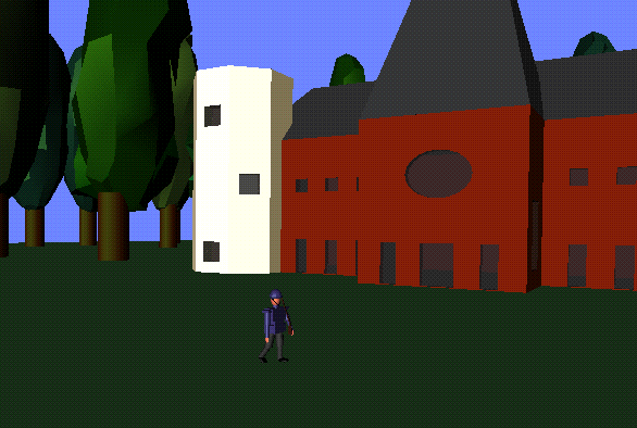
EVENT Walk { }
DEF littleGuard Artifact {
    Behavior {
        InterpolationEngine {
            rotations [ 0.0 1.0 0.0 0.0,
                        0.0 -1.0 0.0 1.5708,
                        0.0 -1.0 0.0 1.5708,
                        0.0 1.0 0.0 0.0,
                        0.0 1.0 0.0 0.0,
                        0.0 1.0 0.0 1.5708,
                        0.0 1.0 0.0 1.5708,
                        0.0 1.0 0.0 0.0    ]
            translations [ 0.0 0.0 0.0,
                           0.0 0.0 0.0,
                           10.0 0.0 0.0,
                           10.0 0.0 0.0,
                           10.0 0.0 0.0,
                           10.0 0.0 0.0,
                           0.0 0.0 0.0,
                           0.0 0.0 0.0  ]
            timeSlices [ 1.0, 10.0, 1.0, 60.0, 1.0, 10.0, 1.0, 60.0]
        }
        Action {
            outputs trans Transformation {
                translation translationValue
                rotation rotationValue
            }
        }
        Action {
            outputs walk Walk {
                recipients [ .leftLeg,
                             .rightLeg,
                             .*leftLowerLeg,
                             .*rightLowerLeg  ]
            }
            condition timeValue == 1.0 || timeValue == 73.0
        }
    DEF body Artifact {
        ...
    }
    DEF leftLeg Artifact {
        Behavior {
            Activator {
                inputs Walk walk
            }
            Deactivator {
                inputs Walk walk
            }
            InterpolationEngine {
                rotations [ 1.0 0.0 0.0 0.0,
                            1.0 0.0 0.0 0.35,
                            -1.0 0.0 0.0 0.17 ]
                timeSlices [ 0.25, 0.5, 0.25 ]
                repeat TRUE
            }
            Action {
                outputs rotation rotationValue
                }
            }
        }
        ...  # upper left leg shape
        DEF leftLowerLeg Artifact {
            Behavior {
                Activator {
                    inputs Walk walk
                }
                Deactivator {
                    inputs Walk walk
                }
                InterpolationEngine {
                    rotations [ -1.0 0.0 0.0 0.0,
                                1.0 0.0 0.0 0.5  ]
                    timeSlices [ 0.25, 0.75 ]
                    repeat TRUE
                }
                Action {
                    outputs rotation rotationValue
                    }
                }
            }
            ...  # lower left leg shape
        }
    DEF rightLeg Artifact {
        ... # same as left leg
        DEF rightLowerLeg Artifact {
            ...
        }
    }
}
The behavior of the right leg is pretty much the same as that of the left leg - except the rotation values of the interpolation engine have a different order. In this example we use a simple user-defined Walk event for activation as well for deactivation of the walking behavior. Usually you would rather add a SFBool field to the event to be sure, if it activates or deactivates the behavior of the recipient.
This is the robot artifact shown in the artifact section. Since each part of the robot has a certain functionality, all these parts will be defined as artifacts. The robot now can be controled by behaviors added to the individual artifacts or the main artifact of the robot.
EVENT Grab { }
EVENT Release { }
EVENT Attach {
    SFEnum [ LEFT, RIGHT ] which
    SFAddress object
}

CLASS LeftGrab {               # attached to the left gribber
    Activate {
        inputs Grab grab
    }
    Deactivate {
        inputs Collision collision
    }
    InterpolationEngine {
        translations [ 0.0 0.0 0.0 ,
                       0.1 0.0 0.0 ]
    }
}

CLASS LeftRelease {               # attached to the left gribber
    Activate {
        inputs Release release
    }
    InterpolationEngine {
        translations [ 0.0 0.0 0.0 ,
                       -0.1 0.0 0.0 ]
    }
}

CLASS Release {
    Trigger {
        inputs Collision collision
        condition type == NONE
    }
    Action {
        outputs MoveNode move {
            destination *                   # scene top level
            recipients *Robot*gripper.grabbed.?
    }

CLASS RightGrab {              # attached to the right gribber
    Activate {
               inputs Grab grab
    }
    Deactivate {
               inputs Collision collision
    }
    DEF engine InterpolationEngine {
               translations [ 0.0 0.0 0.0 ,
                                 -0.1 0.0 0.0 ]
    }
    Action {
        conditions engine.active == FALSE
        outputs Attach attach {
            which LEFT
            object collison.object
            reipients ..    # parent artifact (gripper)
        }
   }
}
CLASS AttachObject {
    Trigger {
        inputs [ Attach attach1,
                 Attach attach2  ]
        conditions attach1.which != attach2.which   # one event from each side
    }
    Action {
        outputs MoveObject move {
            where *Robot*gripper.grabbed
            recipients (attach1.object)
       }
}

DEF Robot Artifact {
    Behavior {
        ...        # sorry, this part is still missing
    }
    Transform { ... }
    Material { ... }
    DEF base Artifact {
        Transform { ... }
        Cylinder { radius   0.4 height  0.1 }
        DEF arm1 Artifact {
            Transform { ... }
            Cylinder { radius   0.15 height 0.6 }
            DEF joint1 Artifact {
                Transform { ... }
                Cylinder { radius   0.15 height 0.3 }
                DEF arm2 Artifact {
                    Transform { ... }
                    Cylinder { radius   0.1 height  0.6 }
                    DEF joint2 Artifact {
                        Transform { ... }
                        Cylinder { radius   0.08 height 0.2 }
                        DEF arm3 Artifact {
                            Transform { ... }
                            Cylinder { radius   0.08 height 0.4 }
                            DEF joint3 Artifact {
                                Transform { ... }
                                Cylinder { radius   0.08 height 0.16 }
                                DEF arm4 Artifact {
                                    Transform { ... }
                                    Cylinder { radius   0.05 height 0.3 }
                                    joint4 Artifact {
                                        Transform { ... }
                                        Cylinder { radius   0.1 height  0.1 }
                                        DEF gripper Artifact {
                                            AttachObject { }
                                            Transform { ... }
                                            Cube { width    0.3 height  0.1 depth   0.1 }
                                            DEF leftgrip Artifact {
                                                LeftGrab { }
                                                Release { }
                                                Transform { ... }
                                                Cube { width    0.05 height 0.2 depth 0.1 }
                                            }
                                            DEF rightgrip Artifact {
                                                RightGrab { }
                                                Release { }
                                                Transform { ... }
                                                Cube { width    0.05 height 0.2 depth 0.1 }
                                            }
                                            DEF grabbed Artifact {
                                                # place holder for grabed object
                                            }
                                        }
                                    }
                                }
                            }
                        }
                    }
                }
            }
        }
    }

    DEF Table Artifact {
        Transform { }
        Cube { width 1.0 height 0.3 depth 0.5 }
    }

    DEF Piece Artifact {
        Transform { }
        Cube { width 0.1 depth 0.1 height 0.3 }
    }
}
If the robot arms are positioned correctly ( kinematics might be realized by a script to achieve this), any object can be grabbed by sending a Grab event and released by sending a Release event. To grab an object requires an collision of the object with both fingers of the gripper, when they are moved towards the center. The object then is attached to the gripper. Thus moving the arms of the robot will move the object. When releasing the object, the gripper fingers are opened and the object is attached to the top level node of the scene. However, this example could easily be changed to attach the object to other parts (e.g. to put it back on the table).
The mailtool is a simple 3D mail watcher connected to an external daemon by an Interface node. The daemon watches the user's mailbox and sends appropriate events to the interface.
EVENT MailBoxState {
    SFBool newMail TRUE
}

...
DEF MailBox Artifact {
    ...
    IndexedFaceSet { ... }  # mailbox shape
    DEF Flag Artifact {
        Behavior {
            Trigger {
                inputs [ MailBoxState state ]
            }
            Action {
                outputs [ Rotate newRot { rotation 0.0 0.0 1.0 1.57 } ]
                condition state.newMail &&
                          (USE Flag.transform.rotation == 0.0 0.0 1.0 0.0)
            }
             Action {
                outputs [ Rotate newRot { rotation 0.0 0.0 -1.0 1.57 } ]
                condition state.newMail &&
                          (USE Flag.transform.rotation == 0.0 0.0 1.0 1.57)
            }
       transform Transform {
                     ...
                     rotation 0.0 0.0 1.0 0.0
                 }
        ...                 # flag shape
    }
}
...
Interface {
    forward [ MailBox.Flag ]
    service "mailWatcher"
}
...
The action components in this example use the USE mechanism to check the current rotation of the mailbox flag. This is completely legal within our specification. Nevertheless we usually recommend to use Query components to achieve a more flexible behavior definition, which allows us to rellocate (rename) the artifacts without any modification to the behavior.
This section describes the file naming and MIME conventions to be used in building VRML browsers and configuring WWW browsers to work with them.
The file extension for VMRL files is .wrl (for world).
The MIME type for VRML files is defined as follows:
x-world/x-vrml
The MIME major type for 3D world descriptions is x-world. The MIME minor type for VRML documents is x-vrml. Other 3D world descriptions, such as oogl for The Geometry Center's Object-Oriented Geometry Language, or iv, for SGI's Open Inventor ASCII format, can be supported by using different MIME minor types.
It is anticipated that the official type will change to "model/vrml", at this time servers should present files as being of type x-world/x-vrml, browsers should recognise both x-world/x-vrml and model/vrml.
A naming scheme to support hierarchical names including wild cards is used to specify artifacts. This is necessary in order to specify the recipients of events.
An artifact path or address is a concatenation of artifact and group node names or classes separated by dots ".". Single names or classes can be replaced by "?", several names or classes in a chain by "*". Addresses starting with "." refer to the local artifact, ".." to the parent artifact and so on. All other paths start at the top level of the artifact graph (which usually is a subset of the scene graph). Field values which are part of an address have to be surrounded by parenthesis "()". Avatars can be addressed using the avatar id, since avatars are not part of the scene graph. Since arbitrary strings are allowed for the avatar id it has to be embedded into double quotes ("avatarId"). Services specified by Interface nodes are specified similar. Avatars and services share a single name space.
Syntactically valid paths/addresses are:
*                  all artifacts of the current scene
?                  top level artifact/separator of the scene
*myObject          all artifacts with the name "myObject" in the scene
*myObject*         "myObject" and its child artifacts
*myObject.*        child artifacts of "myObject" only
*myObject.?        direct children of "myObject"
.                  parent artifact
..                 grandparent artifact
..*                grandparent artifact and all its child artifacts
MeetingWorld.CenterBuilding.3rdLevel.conferenceRoom.Chair
MeetingWorld.CenterBuilding.3rdLevel*
*Teapot..          parent artifact of "Teapot"
"mike@foo.org".Helicopter    sub-artifact "Helicopter" of avatar
"mailBox"          service specification
(member.node).transform      transform field of address specified in the node
                             field of an event with the identifier "member"
These paths/addresses are not valid:
*..
**
*CenterBuilding**Chair
Should we use a special wild character for parent nodes, e.g. "^" to specify arbitrary parent nodes? This seems to be useful when using scene graph events.
This naming scheme also allows us to address single (non-artifact) nodes as well as single fields.
nodeAddress: artifactAddress.nodeName
fieldAddress: nodeAddress.fieldName
Qualified names may be stored in SFAddress or MFAddress fields.
In this section we want to show how events are distributed and how recipient specifications are resolved.
The default recipients of most events are the local artifacts or group nodes. Only system events are sent to the appropriate nodes.
Recipients of events are usually the nodes specified by the recipients field. These nodes can receive events of the particular node event type and field event types only. Additionally events influending a single node may be sent to group nodes (Separators, Artifacts, etc.) which will pass them to the appropriate child nodes. All events sent to a group node will be evaluated by the behavior nodes of the group, before passing them any further.
Senders of nodes are usually the artifacts (or group nodes) the sending behavior node belongs to. Senders of query events (specified by query or sensor components) are the nodes specified in the correspoinding recipients (source) fields.
In shared distributed worlds all events changing at least one field of a node require a message to the shared copies of the virtual environment. However, events generated by time dependent behavior should not be distributed, in order to reduce network traffic. Nevertheless engines or other timers have to be synchronized from time to time. Some behaviors might rather be synchronized on higher levels in order to reduce the number of distributed events.
Our model can easily be extended to meet this requirements. Synchronization of events can be done on four different levels:
To realize behavior within script nodes some basic interfaces not provided by the component mechanism have to be defined. All script nodes share the name space of the behavior node. Thus they can access the appropriate fields. How this is done, may depend on the scripting language. Although outputs and queries of events can be specified and performed within scripts, we do not recommend this, since it makes the interface of the script component less clear and does not allow the browser to optimize event distribution based on the defined inputs and outputs.
We will show the rough key concepts of a scripting interface for C, C++ and Java here:
Events use the same fields as when defined within a VRML file.
Event defintions:
EvNode eventName;
EvField fieldEventName;
EvCopyNode
EvMoveNode
...
Each event contains the following fields:
typedef struct {
    ... /* event dependent fields */
    SFTime timeStamp;
    SFAddress sender;
    MFAddress recipients;
    SFEnum transformModifier;
    SFBool query;
} event;
To define query events, the query field (SFBool) of an event hat to be set to TRUE.
Example:
EvCube cubeEvent;
EvTransform transEvent;

cubeEvent.height = 2.0;
cubeEvent.recipients[0] = "myWorld*lights";

transEvent.query = TRUE;
Sending events:
SendEvent( eventName);
Example:
SendEvent( cubeEvent);
QvQuery types realize Query components within a scripting language. In addition to query components, scripting allows to consider multiple return values, using multi query types.
QvQuery queryName;
QvMultiQuery queryName
Start query execution:
ExecuteQuery( queryName)
Example:
QvQuery transformQuery;
ExecuteQuery (transformQuery);
Events use the same fields as when defined within a VRML file.
Event defintions:
EvNode nodeEventName;
EvField fieldEventName;
...
Each event class contains the following members:
class event {
    public:
    enum transformModifierEnum { NONE, LOCAL, GLOBAL, RELATIVE };
    ... /* event dependent fields */
    SFTime timeStamp;
    SFAddress sender;
    MFAddress recipients;
    transformModifierEnum transformModifier;
    SFBool query;
};
Example:
EvCube *cubeEvent = new EvCube;

cubeEvent->width = 1.0;

cubeEvent->recipients[0] = "LivingRoom.floor";|
Sending events:
eventName.SendEvent();
Example:
cubeEvent->SendEvent();
QvQuery types realize Query components within a scripting language. In addition to query components, scripting allows to consider multiple return values.
QvQuery queryName;
QvMultiQuery queryName
Start query execution:
queryName.Execute()
Example:
#include <vrml.h>
float maxPosX = 0;

EvTransform *carEvent = new EvTransform;
carEvent->recipients[0] = "MyWorld.Cars*";
carEvent->transformModifier = EvTransform::GLOBAL;


QvMultiQuery *getCars = new QvMultiQuery();
getCars->source[0] = carEvent;

// get all specified Objects
getCars.Execute();

for (int i=0; i < getCars->counts(); i++) {
   SFVec3f pos = ((EvTransform *)
   getCars->inputs[0][i])->translation.getValue();
   if (pos[0] > maxPosX)  // x-Value
       maxPosX = pos[0];
}

if (maxPosX==0)
     <Action sendEvent ... >
else if (maxPosX>1000)
     <Action sendEvent ...>
...
Events use the same fields as when defined within a VRML file.
EvNode nodeEventName;
EvField fieldEventName;
...

EvCube cubeEvent = new EvCube();

cubeEvent.setWidth(1.0);

cubeEvent.recipients[0] = "LivingRoom.floor";
Sending events:
eventName.SendEvent();
Example:
cubeEvent.SendEvent();
We want to thank the the VAG for their work on the VRML 1.1 specification, which we think is a very good base for VRML 2.0. Further on we want to thank everybody who sent us comments and contributions to our work and so helped us to see problems from different points of view.
The draft of the VRML 1.1 proposal by the VAG:
http://vag.vrml/org/vrml-1.1.html
The draft of the ISO UTF-8 proposal is online at: http://www.stonehand.com/unicode/standard/wg2n1036.html
The draft for making HTML internationalized is online. We are not as constrained as HTML, since VRML will rarely be primarily text. We can be a little less efficient. ftp://ftp.alis.com/pub/ietf/html/draft-ietf-html-i18n-00.txt
ftp://ftp.isi.edu/in-notes/rfc1766.txt
OpenGL specification and man pages are online: http://www.sgi.com/Technology/openGL/spec.html